Continue to Site

Welcome to our site!

Electro Tech is an online community (with over 170,000 members) who enjoy talking about and building electronic circuits, projects and gadgets. To participate you need to register. Registration is free. Click here to register now.

  • Welcome to our site! Electro Tech is an online community (with over 170,000 members) who enjoy talking about and building electronic circuits, projects and gadgets. To participate you need to register. Registration is free. Click here to register now.

I need HELP in my '4-Bit binary adder' pic16f84 simple project !!!!!!!!

Status
Not open for further replies.

hmahanna

New Member
Hi guys ......

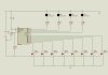
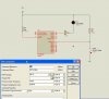
I am still learning my self "how pic Microcontrollers works ??!!!" , i tried some simple projects in ISIS to apply what i have just learned ..... but the result was not good .... i tried to apply the 4-bit binary adder with pic 16f84a and it doesn't work ...... it seems to be that i am sure about my assembly code and the schematic connections ..... i uploaded my simple project for u to check it if you don't mind helping me .

with my all best wishes friends and i am waiting for your feedbacks.
 

Attachments

  • bin adder.asm
    805 bytes · Views: 144
  • bin adder.HEX
    120 bytes · Views: 116
  • bin adder.jpg
    bin adder.jpg
    80.2 KB · Views: 190
Hi

Try this bit of code - I've corrected some points highlighted - so it builds ok.

Have not run your Main code to check the logic of all your addition routine - will leave you to do that.

Have fun..

Code:
;************************************
; written by: *
; date: *
; version: *
; file saved as: *
; for PIC… *
; clock frequency: *
;************************************
; PROGRAM FUNCTION: _______________________________________
;______________________________________________________________

	list p=16F84A
	include "p16F84A.inc"
	
	;============
	
	; Declarations:
	
porta	EQU	05		; not needed  - specified in the include 16f84A
portb	EQU	06      ; not needed  - specified in the include 16f84A

; use registers
   
op		EQU	0c


	org 0x00			; NEW CODE

	goto 	Start		; NEW CODE
	         
	        
	;===========
	
	; Subroutines:
	
Init
	
		banksel	 TRISA   ;NEW CODE  - to select the correct "BANK"
		movlw	b'0000'
		movwf	TRISA
	
		movlw	b'11111111'
		movwf 	TRISB

		banksel	0		; NEW CODE  - to return to BANK 0
		
		retlw	0
	;=============
	
	; Program Start:
	
Start	call	Init
	
	
Main	movf	portb,w
		andlw	b'00001111'
		movwf	op
	
		swapf	portb,F
		movf	portb,w
		andlw	b'00001111'
		
		addwf	op,F
		movf	op,w
		movwf	porta
	    goto	Main 

		END


Opps, missed your Isis Diagram - that will not work ! - will post a new diagram in a few mins
 
Last edited:
Hi,

Here is a diagram for your Simulation, just one led and switch shown.

Note that you do not need to show the battery or the oscillator.

If you Right click on the 84A it opens the window shown.

In there you can specify what osc frequency you want.
In the line above , Program File you can Browse and point it to your .hex file.

You will need to check the Logic state of the switches against your program code, when they are Open the resistors pulls them up to 1, when the switch is closed it becomes 0.
 

Attachments

  • ScreenShot003.jpg
    ScreenShot003.jpg
    53.8 KB · Views: 171
Status
Not open for further replies.

New Articles From Microcontroller Tips

Back
Top