Continue to Site

Welcome to our site!

Electro Tech is an online community (with over 170,000 members) who enjoy talking about and building electronic circuits, projects and gadgets. To participate you need to register. Registration is free. Click here to register now.

  • Welcome to our site! Electro Tech is an online community (with over 170,000 members) who enjoy talking about and building electronic circuits, projects and gadgets. To participate you need to register. Registration is free. Click here to register now.

i need help building a circuit

Status
Not open for further replies.
Yep, I guess yr truck is 24v, so the LM7805 is fine, you might fit a heatsink to the LM7805 tho. You should be able to find a kit that has all these parts included, easy as.
Sweeet, i should have a heat sink laying around, 2.5 amp fuse should be fine right? probably over kill for that screen.
 
Last edited:
I'm not 100% sure if not could I just run a cable off the -V from the bat to the com?

Get a voltmeter, touch the chassis with the negative meter lead and the battery positive terminal with the meters positive lead.

IF the meter indicates 12V then the chassis is negative.
 
Yea I got the com from the bike frame. Only prob is that it didn't work was showing 19V peak and about 11V bottom. Any clue what to do.
I'm gonna try and run a small 12V battery and charger combo see if I can get that to work. I'm lossing the plot with this thing :)
 
Ok ok I seam closer with my new way uesing a small 12V battery and a auto shut off charger running off my bikes dc output.
only problem is charger output peaks at 17 volts.how can I shave off 2volts. Resistor? Or is there a way of keeping the charger connected but stopping the power
At the battery and uesing the power stored in the battery to run the HID kit????
 
could i use a Potentiometer to adjust it? if so what type do i need, rember i buy all my stuff from maplin Maplin Electronics â„¢ Website- USB Turntable iTT 05 XL if you could find what i need i would be happy

hi,
Dont use a resistor.

Use a couple of diodes in series to the battery +V terminal, they will drop between 1.4v and 2V.
Before you do that, measure the charging current at the 17V level, this will indicate the current capacity requirement of the diodes .

BTW: was that 17V measured with the 12V battery connected.???

If you are adding an extra battery, you should check that when the engine is not running that the battery dosn't discharge back thru the generator, usually a series blocking diode is fitted.
 
Hi ya thanks again for the help. I'm gonna use a inline switch to stop any loss when the bike is not running.
You say "measure the charging current at the 17V level, this will indicate the current capacity requirement of the diodes" how would I do this I don't understand 100%
Affter doing this how will I no what diode to use?
Thanks againm

Jim

hi Jim,
Regarding the inline switch, if you fit a blocking diode, you dont have to use a switch.

Do the following:
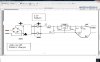
Disconnect the postive lead to the battery, with bike engine stopped.
Connect an ammeter is series with positive terminal of the battery and the wire you have just disconnected.

NOTE:
if the ammeter shows a heavy reverse current when the engine is not running, it most likely means the battery is discharging back thru the generator. So the diode shown in the diagram should be fitted.
Choose a diode,,, 50V [or greater] 10amp[ or greater].

Set the ammeter to 10amps.[dc]
Start the bike engine and read the charge current on the meter.
Tell us what you read, then we can recommend a diode.
 

Attachments

  • Image1.png
    Image1.png
    3.5 KB · Views: 151
Ho ya I couldn't get a reading they way you saoid to do it but I got 0.28 A when I ran the meter +to+ and -to- from the power source..
 
Ho ya I couldn't get a reading they way you saoid to do it but I got 0.28 A when I ran the meter +to+ and -to- from the power source..

Can you post a diagram showing how you connected the meter.?
 
**broken link removed**

i ran the meter between the voltage rectifier and the auto charger in parallel and it read 0.28A and got the same max reading between the autocharger and the battery and the same for between the battery and the HID kit. the hid kit is not in place yet as i have blown 2 up so far im uesing a lamp at the moment
 
AND ON THE 30th "or so" DAY GOD SAID LET THERE BE LIGHT AND. THERE WAS LIGHT. Thank yu so much 4 helping all working. Might not be the right way but its working wht more can I say. Thank you so verrrrrrrrrry much your a true gent.
 
if the 9-22 volts is generated by an alternator (yes obviously it is) then the peak voltage of 9 VRMS is 9 X 1.414 + 12.7 so with a bit capacitor on the input you may just be able to maintain 12 volts input and have and output of 10 volts
 
its now 2.30am arghhhh been in my garage all night to get ready 4 a big xmas ride in the morning. all was ok till the test ride were at higher RPM the light would cut out. its set up as shown below but with 2 diodes on the + just before the bat charger to drop the volts dow and they stay at or about 12V now. could it be that the bike is drawing power back out????? and what should i use to stop this rember i get all my parts from Maplin Electronics â„¢ Website- USB Turntable iTT 05 XL
 
Status
Not open for further replies.

Latest threads

New Articles From Microcontroller Tips

Back
Top