Continue to Site

Welcome to our site!

Electro Tech is an online community (with over 170,000 members) who enjoy talking about and building electronic circuits, projects and gadgets. To participate you need to register. Registration is free. Click here to register now.

  • Welcome to our site! Electro Tech is an online community (with over 170,000 members) who enjoy talking about and building electronic circuits, projects and gadgets. To participate you need to register. Registration is free. Click here to register now.

I did it , But!!!

Status
Not open for further replies.

1Steveo

New Member
I finaly program my first working PIC chip 12f629

But it is geting somekind random in put on the input pin unless i use a reastior on the pin! ( tied to postive )

I was Trying to use a little parts as possible

Must i tie all unused pins to ground like a CMOS chip?


TIA
Steve
 
Some PICs have "week pull ups" these can be enabled normally in the option register.

Un-used pins can be left to float, enless you have enabled MCLR (in the configuration word) if its enabled, that pin must be driven high.
 
1Steveo said:
I finaly program my first working PIC chip 12f629

But it is geting somekind random in put on the input pin unless i use a reastior on the pin! ( tied to postive )

I was Trying to use a little parts as possible

Must i tie all unused pins to ground like a CMOS chip?


TIA
Steve

You can set all unused pins as outputs, that avoids any problems. If the pin you're using as an input is having problems, you will need to do 'something' with it - what are you trying to connect to it?, how about posting a piece of the circuit.
 
Circut

Here it is
 

Attachments

  • pir.JPG
    pir.JPG
    15.6 KB · Views: 528
I'm not suprised it doesn't work, I don't understand the left hand one at all?, and the right hand one hasn't got any pull-up to enable it to work.

You only need one resistor for each pin as a pull-up, fed directly from the output of the opto-coupler. When the opto-coupler is on, the pin will be low, when it's off the pin will be high - you write your program accordingly.

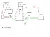
Here's a quick circuit, the photo-transistor is the one inside the opto-coupler.
 

Attachments

  • temp_638.gif
    temp_638.gif
    1 KB · Views: 501
Hello all,
Quick question for Nigel. Apologies if slightly off topic! What program do u use for your schematics?
Thank you for your time.
Barry
 
Barry said:
Hello all,
Quick question for Nigel. Apologies if slightly off topic! What program do u use for your schematics?
Thank you for your time.
Barry

This one was done using the PCB123 software, it was to hand and is fairly fast to use.
 
Status
Not open for further replies.

Latest threads

New Articles From Microcontroller Tips

Back
Top