Continue to Site

Welcome to our site!

Electro Tech is an online community (with over 170,000 members) who enjoy talking about and building electronic circuits, projects and gadgets. To participate you need to register. Registration is free. Click here to register now.

  • Welcome to our site! Electro Tech is an online community (with over 170,000 members) who enjoy talking about and building electronic circuits, projects and gadgets. To participate you need to register. Registration is free. Click here to register now.

I am trying to understand why 3 phase transformers work?

Status
Not open for further replies.

gary350

Well-Known Member
The primary and secondary are wound together on an E I core just like a single phase transformer. It seems to me when L1 gets a sign wave voltage pulse all 3 sections of the transformer should have output voltage. Same for L2 and L3.

I know a 3 phase generator produces 3 separate voltage sign waves 120 degrees apart. If L1, L2, L3 of the transformer all get a voltage wave 120 degrees apart all 3 coils should all 3 have output all at the same time equaling a total of 9 output waves. Apparently there are not 9 voltage pulses so I am trying to understand why?

I bet if I build an E I transformer with 1 primary coil and 3 secondary's, all 3 secondary coils will have output.
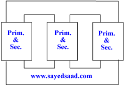
images
 
Last edited:
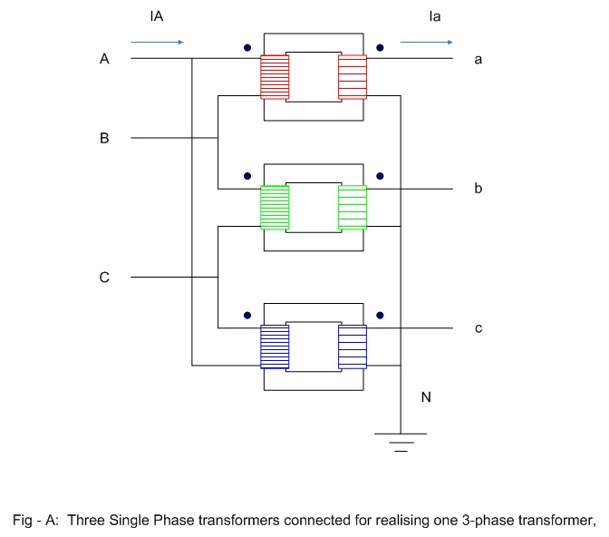
Three phase transformers are actually 3 single phase transformers on the same frame, 3 separate one's work equally well.
If you only have one primary all secondaries will be in phase.
Max.
 
Three phase transformers are actually 3 single phase transformers on the same frame, 3 separate one's work equally well.
If you only have one primary all secondaries will be in phase.
Max.


I understand that. When L1 primary gets voltage wave then L1, L2, L3 will all have an output. Same for L2 and L3. So there are 9 outputs just like I thought. How does a 3 phase motor run if it receives 9 voltage waves?
 
Where do you get the '9 voltage waves'?
3 distinct in 3 distinct out.
Max.
 
Last edited:
Another Explanation and a link.

The three available voltages, which themselves are each displaced from the other by 120 electrical degrees, not only decided on the type of the electrical connections used on both the primary and secondary sides, but determine the flow of the transformers currents.
With three single-phase transformers connected together, the magnetic flux’s in the three transformers differ in phase by 120 time-degrees. With a single the three-phase transformer there are three magnetic flux’s in the core differing in time-phase also by 120 degrees.

**broken link removed**
Max.
 
I can see how that will work the magnetic field from each primary only effects the secondary on the same core.

Otherwise you would able to distinguish the output between three separate transformers and a combined core type.
Max.
 
In a single phase transformer, with typical EI core like this:-

**broken link removed**

The centre has the winding and the sides are there to close the magnetic circuit for the flux, and the flux in the two sides adds up to the flux in the centre.

In a three phase transformer there are three main magnetic cores, and on each of them the primary voltage of one phase will be transformed to the secondary voltage of the same phase.

In all transformers of that type there has to be a complete circuit for the flux. However, in a three phase transformer the total instantaneous flux from all three phases added together is always zero, so there is no need for the side part of that is needed with a single phase transformer.

If a three phase transformer were used on three signals that were different, that did not add up to zero at all times, it wouldn't work properly, and it would need to be made with a return path, or three separate single-phase transformers could be used.
 
Where do you get the '9 voltage waves'?
3 distinct in 3 distinct out.
Max.

Actually with the right winding configurations you can get 1 to 12 and more phases out of a EI core three phase transformer. ;)
 
Actually with the right winding configurations you can get 1 to 12 and more phases out of a EI core three phase transformer. ;)
Maybe I can remember how this works.
1 diode you get 60 hz noise in you power supply. 1X
4 diodes (full wave) you get 120hz noise. 2X
If you use 4 diodes on a phase 1 winding, +4 diodes on phase 2 winding + 4 diodes on phase 3 winding you get 6x noise.
I had a transformer with both Delta and Y windings. The Delta and Y windings produce noise one notch out of phase. By having 3(full wave bridges in Delta) added to 3(full wave bridges in Y) you again double the noise frequency.

I had a large broadcast transmitter running in Delta+Y full wave bridge power supply. One day the filter capacitor blew up. (about 5 gallon jug size) I could not get one right away so we ran with out a filter cap. Because the power supply has the equivalent to 12 phase power there was little ripple.
 
Yep. Most any center tapped Wye configuration will give you 6 phase power which when rectified gives a pretty low 720 Hz ripple. Toss a second offset Delta on top of that and you can get 6 more phase splits between the first six giving you the 12 you are talking about.

If you really want a wiring headache to figure out put Delta/Wye sub phase splitters between each o those 12 phases and you can get 24 phase out of a single three phase EI core transformer which by all reasonable rectification standards gives you a pretty clean DC! ;)

I've never seen a 24 phase output transformer configurations but I have read about them being used in some high power applications back before today's high power solid state rectification came into being where a typical MG set of the day was too big or impractical for the application.
 
The 60KW transformer we have at work starting buzzing very loud so I shut it down. I poured a can of polyurethane varnish down inside the winding and let it dry over the weekend. The transformer has open air windings with spacers between the layers and the large square wires. The transformer sounds good as new again and would have self destructed if I had not fixed it. It has one EI core with 3 primary coils and 3 secondary coils with several taps. Input voltage is L1=492v L2=493v L3=495v the output is 241v. With all the coils on one common EI core the magnetic field from each primary has to produce a voltage in all 3 secondary coils. There has to be an equal voltage in all 3 secondary coils and the voltage on all 3 coils are in phase. So maybe the 3 phase motor does not care?

I did this experiment. I have 3 identical transformers, 1500 watts, 120v to 240v. I connected all the primary winding in parallel. I wired the secondary coils in the Y configuration making sure they were in phase. I connected this to a 1/2 hp 3 phase motor and all it does is buzz. It wont run. OK so this experiment tells me the motor does not like this.

OK so the 3 phase transformer with 1 common EI core produces 3 identical voltage outputs from the magnetic field of each primary coil and the 3 phase motor runs but it wont run on my 3 separate transformer experiment? I have only duplicate the single phase part of the 3 phase transformer. Apparently a 3 phase motor connected to a 3 phase transformer is capable of ignoring the single phase voltage that it receives.
 
Last edited:
A 3 phase motor will definitely not run on 1ph, any more than a 1ph induction motor will not run on 1ph without some method of phase shift added.
Max.
 
Last edited:
With all the coils on one common EI core the magnetic field from each primary has to produce a voltage in all 3 secondary coils. There has to be an equal voltage in all 3 secondary coils and the voltage on all 3 coils are in phase.

If the transformer is like the ones that I have used, that isn't correct. The normal three phase transformers with EI cores have three legs, a top and a bottom, like this:-
3-phase-transformers-250x250.jpg


The magnetic field in each leg are not in phase with each other. The total magnetic flux from all the windings has to add up to zero, because there is no return leg from the top to the bottom. Normal three-phase supplies, have the amplitudes the same, and each phase separated 120° from the other two, and sinusoidal waveforms. When those conditions are met, the voltages or magnetic fields add up to zero, so no return leg is needed on the transformer.

On a single phase transformer, there is only one voltage or magnetic field, so it can't possibly add up to zero, and there have to be the return legs on the transformer.


Yes it is easy to run 3 phase motors on single phase all do is connect 240 VAC across L1 and L2 with a temporary start capacitor across L2 and L3. When the motor comes up to full speed disconnect the capacitor.

You can also use a single phase motor to get the 3 phase motor up to full speed then apply 240 VAC to L1 and L2 then turn off the single phase motor.

There are several other ways to run a 3 phase motor on single phase it all depends if you want automatic start or manual start and if you want 2/3 power rating or full power with a manual run or automatic rotor motor. I run my Bridgeport mill, lathe, surface grinder and compressor at 2/3 power on a static 3 phase converter with a manual rotor motor. Every thing runs fine at 2/3 power except the surface grinder it needs a rotor motor to make it run at full power.
 
Every thing runs fine at 2/3 power except the surface grinder it needs a rotor motor to make it run at full power.

Or you could just let your lathe or Bridgeport run idle in the back round while using the grinder. Every idling motor adds to the "developed" 3 phase quality.
 
Diver350 is what I'm familiar with. In section 500 of this thing https://www.vesco-usa.com/16 Pin Power Module.PDF , there is that sort of transformer.
3 phase 208/240 at about 60 A is combined to make about 20 kV at about 2A or so. At one point, we had to replace the transformer because of dripping water. It was bolted to a pallet inside of a box. The "big guy" pulled the bolts out of the pallet. "Fun thing" to work on.
 
Status
Not open for further replies.

Latest threads

New Articles From Microcontroller Tips

Back
Top