I have been on this problem for awhile. I have circuit with 3-phase generator inputs, these inputs are sinewaves at varies peak-to-peak voltages (Vpp). No matter the input voltage, the output voltage accross the load (64ohms, 50watt) should be DC or a small (less than 1Vpp) ripple voltage and this DC voltage should be 1 or 2 volts greater than the input peak voltage. In other words, if the input is 27Vpp, the output should be about 11.5V (DC voltage). The input varies between 1Vpp to 30Vpp, but the output should always be few volts higher than the input peak.
My problem is when I input 27Vpp, I get approx. 9.50V at the output, which is not exceptable. I should be getting 11V and a little higher. Also, when I look at output signal with an oscilloscope, I do not see a small peak-to-peak ripple voltage; instead I see about an 7Vpp signal, but the voltage is 9.50V at output.
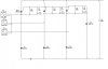
Initially, I thought C4 (22uf, 50V) was not discharging and charging properly, because of the huge peak-to-peak rippleon the output. C4 is suppose to cause the ripple or dc voltage at the output no matter how the input AC input signal varies from 1Vpp to 30Vpp. So, I replaced C4 and same results. I was shocked.
I have three other test boards that output about 11.5V with an input of 27Vpp
So I am thinking half wave rectification of the input signal is not happening before it reaches the capacitor, C4. In other words, I think that too much of the input signal is reach the output and causing C4 not to charge to the signal's peak. Excuse me if that last statment makes no sense.
I have checked all the resistances, capacitance, threshold diode voltage (.65V). The SCR are conducting when triggered by the gate, they get hot at about 20Vpp or more. Somewhere in the circuit i am losing voltage. I do not want to replace the SCR unless I have a good understanding why. i am trying to analyze the failure and then replace.
I attached the circuit below. The ground for the circuit is not the same ground for the 3-pahse generator. The generator is not on the circuit. The circuit is used to reduce power to the load.
So any help would be really great and appreciated. let me know if you need a capture of the output signal or any questions.
My problem is when I input 27Vpp, I get approx. 9.50V at the output, which is not exceptable. I should be getting 11V and a little higher. Also, when I look at output signal with an oscilloscope, I do not see a small peak-to-peak ripple voltage; instead I see about an 7Vpp signal, but the voltage is 9.50V at output.
Initially, I thought C4 (22uf, 50V) was not discharging and charging properly, because of the huge peak-to-peak rippleon the output. C4 is suppose to cause the ripple or dc voltage at the output no matter how the input AC input signal varies from 1Vpp to 30Vpp. So, I replaced C4 and same results. I was shocked.
I have three other test boards that output about 11.5V with an input of 27Vpp
So I am thinking half wave rectification of the input signal is not happening before it reaches the capacitor, C4. In other words, I think that too much of the input signal is reach the output and causing C4 not to charge to the signal's peak. Excuse me if that last statment makes no sense.
I have checked all the resistances, capacitance, threshold diode voltage (.65V). The SCR are conducting when triggered by the gate, they get hot at about 20Vpp or more. Somewhere in the circuit i am losing voltage. I do not want to replace the SCR unless I have a good understanding why. i am trying to analyze the failure and then replace.
I attached the circuit below. The ground for the circuit is not the same ground for the 3-pahse generator. The generator is not on the circuit. The circuit is used to reduce power to the load.
So any help would be really great and appreciated. let me know if you need a capture of the output signal or any questions.