OUTLINE about my bike project
Due to my changing subject on this project and my changing direction I felt a need to post an outline about what the project does, how it works, progress and why I did what I did. A working prototype is presently working except for a few add on's. Am waiting for parts to build a complete working project with enclosures as well.
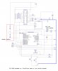
Transmitter board to date as posted is using a daughter board mounted onto a Tap-28 development board with a 18F2420 w/ ext osc.
Board utilizes a Holtek HT12E encoder. Had second thoughts about using a PIC as the encoder would work by itself but utilizing a micro-controller it allows me to incorporate a battery monitor(using PortA.0) and a piezo sounder to alert the user.. The Transmitter is un-powered until a button press to conserve battery power (need to put PIC to SLEEP to conserve more power).
Upon a switch closure, the transmitter is powered and transmits a data stream as per the HT12E.
A P-channel mosfet is included in final design to avoid any reverse polarity issues. A piezo sounder to be incorporated to alert rider.
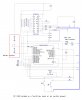
The receiver unit incorporates a PIC that controllers a 5 x 7 LED matrix that is driven by two high side drivers(TD62783APG) for each LED color(RED, GREEN) using 9v in prototype but final design to use 4.5v (need to access this as the voltage may be to low?). The circuit then utilizes a TLC5916/17 constant sink chip which is set to provide a max current draw of 26ma to each segment of the 5 x 7 Bi-color matrix.
The receiver sends the data stream to a Holtek HT12D decoder that is reset after each valid transmission to reset the data latches in the HT12D (the latches will reset upon a valid data stream as per data sheet, which is unacceptable in this application so the Vdd is toggled off then on to reset latches (tried several different configurations but to no avail).
The PIC also incorporates in final design, a battery monitor.
Preliminary tests showed a 150ma draw on the receiver board/LED matrix but experimenting with multiplexing I was able to reduce to 25ma current draw on the matrix only, as at present I need to incorporate a voltage regulator to power the PIC and the LED matrix on one battery source.
The transmitter board at first had a current draw of 8ma standby and 14ma at transmission. After utilizing a port pin to power the transmitter, the standby current draw is 5ma but hopefully by putting the pic to sleep it will lower the standby current draw.
Final design to utilize 18F25K20 pics, all smd and the 5 x 7 Kingbright LED matrix.