Continue to Site

Welcome to our site!

Electro Tech is an online community (with over 170,000 members) who enjoy talking about and building electronic circuits, projects and gadgets. To participate you need to register. Registration is free. Click here to register now.

  • Welcome to our site! Electro Tech is an online community (with over 170,000 members) who enjoy talking about and building electronic circuits, projects and gadgets. To participate you need to register. Registration is free. Click here to register now.

HT12D and HT12E encoder/decoder issues

Status
Not open for further replies.
Here one for the road

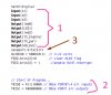
Spending too much time in the ISR
Don't use delays, write to slow peripherals like LCDs, write to EEPROM, or perform other time-consuming tasks in the ISR. If you have an interrupt that occurs more quickly than one of these tasks, your application never gets out of the ISR and your main code never runs.
 
Its a done deal IN then OUT

Looks easier to read for sure. Working on the HLVD then an audible alert.So far everything still works as planned. I made a mis calculation on my meter. Had set on 400ma setting so .3ma is actually 3ma when I switch to 4ma scale but I know at one point I had .4ma on the 4ma scale. Need to find out why. It appears to be going into SLEEP but ?

Code:
'xxxxxxxxxxxxxxxxxxxx
'interrupt
'xxxxxxxxxxxxxxxxxxxxx
Interrupt PORTB_Change()
 Save(0) // Save the system variables
 If RBIF = 1 Then // Check if the interrupt was a PORTB change
 RBIF = 0
 WREG = PORTB // Be sure to read the contents of PORTB to
 // clear the mismatch
 WhatTheHellButtonWasPressed = PORTB 
     
 // PORTB 7:4 has changed, do what you want here...
 EndIf
 Restore // Restore the system variables
End Interr
 
Well, you posted enough of the code to show pretty much nothing. At least you finally got the interrupt routine right.
 
YES BUT the pic is not SLEEPING

been investigating WHY the meter shows 3ma durring SLEEP or supposed SLEEP.
Went back to square one
Code:
'xxxxxxxxxxxxxxxxxxxx
'interrupt
'xxxxxxxxxxxxxxxxxxxxx
Interrupt PORTB_Change()
 Save(0) // Save the system variables
 If RBIF = 1 Then // Check if the interrupt was a PORTB change
 RBIF = 0
 WREG = PORTB // Be sure to read the contents of PORTB to
 // clear the mismatch
 s2 = PORTB 
     
 // PORTB 7:4 has changed, do what you want here...
 EndIf
 Restore // Restore the system variables
End Interrupt

  
Sub PORTB_Interrupts(Control As Boolean) // Small routine to enable/disable PORTB Interrupts.
 If Control = True Then 
 RBIE = 1 //  interrupt enable bit
 Enable(PORTB_Change)
  
 Else 
 
 RBIE = 0 //  port change interrupt enable bit
 Disable(PORTB_Change) //
 EndIf //
End Sub

then
Code:
While True // Infinite loop

 PORTB_Interrupts(True) // Enable PORTB interrupts

 If s2  = 0 Then
 enable (portb_Change)
      led0 = 0
      DelayMS(2000)
      Toggle(led0)
      Else 
      led0=1
End If


    Sleep // Put the PIC to sleep and wait for a change
 // on PORTB 7:4
Wend

but meter still shows 3ma.
Running Grahams INTERRUPT ON PORTB it shows .03ma on the 4ma scale
Looking at Grahams code it has the sub(PORTB_Interrupt(Control as boolean)
But there is no statement calling this subroutine? unless the code just falls through to it?
Trying to get a grasp of what is going on.
 
Do your realize how frustrating and impossible it is to help you? You get something almost working with massive amounts of help, then you throw everything away and start over (while forgetting everything learned in the process).

My own projects are suffering while I attempt to help you. Sorry, can't do it anymore. You need to learn to appreciate all the time people have sacrificed in futile efforts to help you. Sorry, a hastily tossed off "thanks" or even "THANKS" really doesn't do much for me.

Watching the train wrecks is addictive but I can't participate any longer.
 
Well I thought it was going to sleep but it wasn't as you pointed out.
Will keep hacking at it and hopefully get it right
Sorry if I am a bother.
 
I told you about 4 pages back Sleep never happens the way your doing it I told interrupt's don't work like your doing it. Jon's post 129 and my post 127 are basically the same thing. I still don't think you get it.

There four things you need to do to make this work as planned.

1. You set the chip type, clock, and include files.

2 . You set the ISR to do only one thing that's if PORTB changes you save that and store it to a variable that you test in main.

3. You set the PORT's and register's are set right.

4. Let main run in a loop.

This would give you a chance for it all to happen.

Code:
// your main would be like this 
Start_ Interrupt // turns on the PORTB interrupt's 
If change_Happened then // test for change
   // what you want to do goes here
endif
If but_HV = 1 then // then test the battery
  Test_Batt    // sub is called here
endif

//If none of the above is happening 
//I'm taking a nap 

sleep // here  

If change_Happened then
// wake me up
endif
 
As per suggested changes

Here is what I am using for testing of code. BUT I don't think its going into SLEEP?
Getting weird happenings, led blinks then it won't until I disconnect then reconnect.
This should go to SLEEP?
Code:
{
*****************************************************************************
*  Name    : UNTITLED.BAS                                                   *
*  Author  : [select VIEW...EDITOR OPTIONS]                                 *
*  Notice  : Copyright (c) 2013 [select VIEW...EDITOR OPTIONS]              *
*          : All Rights Reserved                                            *
*  Date    : 1/2/2013                                                       *
*  Version : 1.0                                                            *
*  Notes   :  this one works 1/10/2013                                                              *
*          :                                                                *
*****************************************************************************
}


Device = 18F2420
Clock = 8
Config   LVP = OFF, mclre = off
Include "InternalOscillator.bas"
Include "utils.bas"
Dim RBIF As INTCON.0  //port change interupt flag
Dim RBIE As INTCON.3 //port change interupt enable
Dim x As Byte
Dim TX_Enable As PORTC.0
Dim TX_pwr As PORTC.1
Dim GD_bat As PORTC.2
Dim led0 As PORTA.5 // blue
Dim LED1 As PORTC.4  //green
Dim led2 As PORTC.5  //red
Dim s1 As PORTB.6
Dim s2 As PORTB.5
Dim s3 As PORTB.4
Dim saveport As Byte
//Dim  As PORTB.5
   

'xxxxxxxxxxxxxxxxxxxx
'interrupt
'xxxxxxxxxxxxxxxxxxxxx
Interrupt PORTB_Change()
 Save(0) // Save the system variables
 If RBIF = 1 Then // Check if the interrupt was a PORTB change
 RBIF = 0
 WREG = PORTB // Be sure to read the contents of PORTB to
 // clear the mismatch
// PORTB 7:4 has changed, do what you want here...
 saveport = PORTB
 EndIf
 Restore // Restore the system variables
End Interrupt

  
Sub PORTB_Interrupts(Control As Boolean) // Small routine to enable/disable PORTB Interrupts.
 If Control = True Then 
 RBIE = 1 //  interrupt enable bit
 Enable(PORTB_Change)
  
 Else 
 
 RBIE = 0 //  port change interrupt enable bit
 Disable(PORTB_Change) //
 EndIf //
End Sub
Inline Sub Sleep()
 Asm
    Sleep
 End Asm
End Sub
//sssssssssssssssssssssssssssssssssssssssssss

SetAllDigital
Input(s1)
Input(s2)
Input(s3)
Output(led0)
Output(LED1)
Output(led2)
Output(TX_Enable)
Output(TX_pwr)
Output(GD_bat)
saveport.bits(5)=1
HLVDCON = %00010111  // 3.12 volts
PIR2.bits(2)=0       // clear HLVD flag
PIE2.bits(2) = 1      //enable HLVD interrupt


// Start Of Program...
TRISB = %11110000 // Make PORTB7:4 all inputs
TRISC = %00000000 // Make PORTC all outputs

led0 = 1          // turn off all leds
LED1 = 0
led2 = 0
TX_Enable = 1
TX_pwr = 0
GD_bat=0 
While True // Infinite loop


 PORTB_Interrupts(True) // Enable PORTB interrupts
  if saveport.bits(5) = 0 then
  led0 = 0           // turn on led0
  delayms(2000)
  led0 = 1           // turn off led0
  end if 


    Sleep // Put the PIC to sleep and wait for a change
 // on PORTB 7:4
Wend
 
I have only one thing to say your program takes hours to run if it'runs And it don't .
The code you posted can't be what your using you didn't set the On board OSC
look it over and see what you forgot I'll give you a hint

Code:
Device = 18F2420
Clock = 8
Config   LVP = OFF, mclre = off

I tried that code it sit's at sleep. it doesn't wake up with any port change none.
 
Last edited:
EURIKA I got it actually working right

At least this section.
The issue was the meter. Set on 400ma scale the circuit drew .1ma but when I switched to 4ma scale the meter showed 3ma. On the 4ma scale the circuit stopped working after one blink of the LED routine. On the 400ma scale it kept working. I guess the meter went into overload or ?
I ran this posted code but do not have the LED actually coming on. Circuit starts out drawing .191 ma then creeps up to .804ma. If I have the LVP = OFF it pretty much stays under .192 ma
I must apologize for my meter issue. Never knew this meter had this issue of coarse I never had to measure this low of current draw. And just to verify my results, I ran Grahams PORTB CHANGE code and cam up with very similar results.The meter is a Metex ME-11. Very nice meter I aquaried 12 years ago from Radio Shack. It even has an RS232 port which I have never used.
Code:
        {
        *****************************************************************************
        *  Name    : UNTITLED.BAS                                                   *
        *  Author  : [select VIEW...EDITOR OPTIONS]                                 *
        *  Notice  : Copyright (c) 2013 [select VIEW...EDITOR OPTIONS]              *
        *          : All Rights Reserved                                            *
        *  Date    : 1/2/2013                                                       *
        *  Version : 1.0                                                            *
        *  Notes   :  this one works 1/10/2013                                                              *
        *          :                                                                *
        *****************************************************************************
        }


        Device = 18F2420
        Clock = 8
        Config   LVP = Off 
        Include "InternalOscillator.bas"
        Include "utils.bas"
        Dim RBIF As INTCON.0  //port change interupt flag
        Dim RBIE As INTCON.3 //port change interupt enable
        Dim x As Byte
        Dim TX_Enable As PORTC.0
        Dim TX_pwr As PORTC.1
        Dim GD_bat As PORTC.2
        Dim led0 As PORTA.5 // blue
        Dim LED1 As PORTC.4  //green
        Dim led2 As PORTC.5  //red
        Dim s1 As PORTB.6
        Dim s2 As PORTB.5
        Dim s3 As PORTB.4
        Dim saveport As Byte
        //Dim  As PORTB.5
         
         
        'xxxxxxxxxxxxxxxxxxxx
        'interrupt
        'xxxxxxxxxxxxxxxxxxxxx
        Interrupt PORTB_Change()
         Save(0) // Save the system variables
         If RBIF = 1 Then // Check if the interrupt was a PORTB change
         RBIF = 0
         WREG = PORTB // Be sure to read the contents of PORTB to
         // clear the mismatch
        // PORTB 7:4 has changed, do what you want here...
         saveport = PORTB
         EndIf
         Restore // Restore the system variables
        End Interrupt
         
         
        Sub PORTB_Interrupts(Control As Boolean) // Small routine to enable/disable PORTB Interrupts.
         If Control = True Then 
         RBIE = 1 //  interrupt enable bit
         Enable(PORTB_Change)
         
         Else 
         
         RBIE = 0 //  port change interrupt enable bit
         Disable(PORTB_Change) //
         EndIf //
        End Sub
        Inline Sub Sleep()
         Asm
            Sleep
         End Asm
        End Sub
        //sssssssssssssssssssssssssssssssssssssssssss
         
        SetAllDigital
        Input(s1)
        Input(s2)
        Input(s3)
        Output(led0)
        Output(LED1)
        Output(led2)
        Output(TX_Enable)
        Output(TX_pwr)
        Output(GD_bat)
        saveport.bits(5)=1
        HLVDCON = %00010111  // 3.12 volts
        PIR2.bits(2)=0       // clear HLVD flag
        PIE2.bits(2) = 1      //enable HLVD interrupt


        // Start Of Program...
        TRISB = %11110000 // Make PORTB7:4 all inputs
        TRISC = %00000000 // Make PORTC all outputs
         
        led0 = 1          // turn off all leds
        LED1 = 0
        led2 = 0
        TX_Enable = 1
        TX_pwr = 0
        GD_bat=0 
        While True // Infinite loop


         PORTB_Interrupts(True) // Enable PORTB interrupts
          If saveport.bits(5) = 0 Then
          led0 = 1           // turn on led0
          DelayMS(4000)
          led0 = 1           // turn off led0
          RBIE = 1
          End If 


            Sleep // Put the PIC to sleep and wait for a change
         // on PORTB 7:4
        Wend
 
I'm glad to see you got the internal oscillator configuration properly set. Hope you understood Burt's clue.

As I have pointed out numerous times before, using the internal oscillator can be a real trap for those not paying attention to the details. The few cents saved on a crystal and a couple caps far outweighs the time and frustration of finding an internal oscillator setup/configuration error.

It's clear that your code is copy&paste(tm) from several different sources without an in-depth understanding of how the various pieces work. I'm saying this not as a criticism but in the hopes you'll learn something. Example and tutorial code is a good starting point to learn how something works. Usually, directly incorporating it into your code isn't going to work well.

The illustration below (from your latest code posting) shows several different programming styles, so it's clear they came from different places.

(see the attachment)

In the area numbered 1, you set up the various port pins as inputs and outputs using the INPUT() and OUTPUT() commands.

In the area numbered 2, you again set up most of the port pins as inputs and outputs.

Why are you doing this twice? Me thinks it's because you don't understand the code you have copied&pasted(tm). Either of these methods is equally valid but why use both? It can only lead to confusion and errors (you look at the code in one place and think it's set one way but in the other place it's set the other way). I happen to prefer the method of region 1 as easier to understand but either will work. Do note that if you like the method of region 2, you have not set up the outputs for PortA.

The item numbered 3 in the illustration is another area that will lead to (more) confusion. the variable SavePort is set to the upper 4 bits of PortB in the interrupt routine. It's always a good idea to initialize variables, and I realize that you've only coded for whatever action happens on PortB.5. Are you going to remember to add lines to initialize the other bits when you add the remaining code? Wouldn't it just be easier to initialize the entire byte all at once?

SavePort = 0

is much simpler and easier to understand than 3 separate lines initializing separate bits spread all over the place.


LVP - What is LVP and why would you want it enabled??? Hint: You don't. But understanding what it is might prevent mistakes in the future.


I don't believe you're actually doing anything with the HLVD in the code you're shown.


Again, please try to understand what I've posted here. "I'm new at programming and don't understand this stuff" is not going to serve as an excuse much longer. People are getting tired of explaining the same things again and again...you might notice the lack of people replying to your posts. I'm not posting this to be mean; I'm posting it in the hopes that you'll LEARN something and will be able to write code without so much hand-holding.
 

Attachments

  • MrDEB Why oh why.jpg
    MrDEB Why oh why.jpg
    131.5 KB · Views: 182
In my recent post I have not done any copy n paste of other code/. I type in every line. The code was assembled AFTER I experimented with each section to get an understand of what is going on. YES I copy n pasted each section AFTER I found out what it does. I prefer the INPUT OUTPUT statements and after editing these repeats will be gone hopefully.
After looking over my posts from several days ago I could not see why it was not going to sleep, now I know it is.
On the HLVD it appears to be working but after I get the code edited I will run it again to be sure. The code is in the same order that you posted with added bells n whistles.. I used LEDs to indicate when each statement enabled a certain pin.
I wrote the entire TX code section myself so maybe there is hope.
If you read my posts I am following the recommendations of inserting an LED routine to determine code flow which has worked very well.
Question that I am curious about. In the posed code I inserted RBIF = 1 at the end of the led routine. BUT Im under the impression that the sub PORTB_Interrup does this but I am not sure. In other words am I resetting the flag bit again? unnecessarily? Was going to try and omit after I get the code reedited.
 
Oh I forgot the saveport.bits(5)(#3) was used just for testing portb5. No reason to get more clutter than need be. Heaven knows I have enough clutter already.
 
Did I not post something there about tried code in sim your HLVD is not working how the hell would you no.

You press a button led comes on if the voltage is low you have voltage set low when you test button .

Did you try it with voltage at 5 volts ????

deb's.png
 
Last edited:
...On the HLVD it appears to be working but after I get the code edited I will run it again to be sure. The code is in the same order that you posted with added bells n whistles.. I used LEDs to indicate when each statement enabled a certain pin...

If the HLVD routine is working in the code you posted, it's PFM since there's only one LED turned on in the entire collection of lines.

I've offered you some words of advice. Heed them or not as you choose. I don't know how long you screwed around in your recent "do-over" to get the oscillator properly set up, which was discussed in this very topic some pages ago. But I'm certain your efforts to fix it weren't helped by an LED flashing at a one second rate.

Time to stand on your own two feet....
 
I am presently using LED0 for a bad battery indication. As for voltage, I set the trip point in present code at 3.12volts. I then lowered the voltage using the voltage adjustment in MPLAB. Changed it .1 volt at a time until the LED0 led comes on after pressing the s3(test battery switch).
It seems to work but am going to do some further testing to be sure.
The oscillator has been set on internal osc since I assembled a second Tap-28 with out the crystal. As for the LVP I got curious about it and found that with it ON I drew moire current. I found that the LED routine in the while/wend loop was causing the meter issues regardless what the LVP setting was. If you look at the routine, the LED never comes on. Tested this theory against Grahams code and basically same results as the PORTB change code has no LED enabled as well.
If you look at the battery test sub you will see two LEDs.led0 and GD_bat.
As I said it appears to work. YES code needs editing of delays etc. Set up just for testing of code. The sub routine BATTERY_TEST is triggered by s3 on portB.6
Hope this explains what and why I did.
As for understanding why and what, I put the battery test su together by reading Jons example code as well as Burts then instituting what I wanted to do.
Perhaps try it out yourself and maybe I am right that it works but then maybe I am wrong??
Code:
' xxxxxxxxxxxxxxxxxxxxxxxxxx
Sub  BATTERY_TEST()
'xxxxxxxxxxxxxxxxxxxxxxxxxxx
' BAD BATTERY
 If  PIR2.bits(2)=1 Then         // check hlvd flag
    TX_pwr = 1    //turn on transmitter
    led0 = 1     //blue led next to green BI color in final plan
         DelayMS(1000)
    Toggle(led0)
 End If
    PIR2.bits(2)=0
     
 ' GOOD BATTERY
 If PIR2.bits(2)=0 Then
       GD_bat = 1       // green led next to blue GD_bat = good battery
              DelayMS(1000)
       Toggle( GD_bat)
              DelayMS(1000)
       TX_pwr = 0                       //turn off transmitter
    EndIf  
   // PIR2.bits(2)=0    // reset interrupt flag  DO I REALLY NEED TO RESET?
   // RBIF = 0      // Port change interrupt flag bit
End Sub
 
Sorry... I'm done trying to decipher your code. There's nothing I like less than trying to figure out some one's code when it's logically written.. Your logic is a mystery to me.

Ok, so LVP on or off makes a difference. You've cleverly resisted demonstrating any knowledge about what LVP is, and why you might want it on or off. Do you NEED it on? SHOULD it be off? It must mean something. Perhaps if you KNEW what it is, you'd know how and why it should be on or off.

Sorry I can't understand your code. Sorry I can't understand your intentions. Sorry I can't ever tell if you've ever really answered a question somebody who's trying to help has asked.

But since all of your answers are "It seems to work but I could be wrong" it apparently works as well as you expect it to, so you don't need any more help anyway.
 
The code That's been posted this Code
Code:
   {
        *****************************************************************************
        *  Name    : UNTITLED.BAS                                                   *
        *  Author  : [select VIEW...EDITOR OPTIONS]                                 *
        *  Notice  : Copyright (c) 2013 [select VIEW...EDITOR OPTIONS]              *
        *          : All Rights Reserved                                            *
        *  Date    : 1/2/2013                                                       *
        *  Version : 1.0                                                            *
        *  Notes   :  this one works 1/10/2013                                                              *
        *          :                                                                *
        *****************************************************************************
        }


        Device = 18F2420
        Clock = 8
        Config   LVP = Off 
        Include "InternalOscillator.bas"
        Include "utils.bas"
        Dim RBIF As INTCON.0  //port change interupt flag
        Dim RBIE As INTCON.3 //port change interupt enable
        Dim x As Byte
        Dim TX_Enable As PORTC.0
        Dim TX_pwr As PORTC.1
        Dim GD_bat As PORTC.2
        Dim led0 As PORTA.5 // blue
        Dim LED1 As PORTC.4  //green
        Dim led2 As PORTC.5  //red
        Dim s1 As PORTB.6
        Dim s2 As PORTB.5
        Dim s3 As PORTB.4
        Dim saveport As Byte
        //Dim  As PORTB.5
 
 
        'xxxxxxxxxxxxxxxxxxxx
        'interrupt
        'xxxxxxxxxxxxxxxxxxxxx
        Interrupt PORTB_Change()
         Save(0) // Save the system variables
         If RBIF = 1 Then // Check if the interrupt was a PORTB change
         RBIF = 0
         WREG = PORTB // Be sure to read the contents of PORTB to
         // clear the mismatch
        // PORTB 7:4 has changed, do what you want here...
         saveport = PORTB
         EndIf
         Restore // Restore the system variables
        End Interrupt
 
 
        Sub PORTB_Interrupts(Control As Boolean) // Small routine to enable/disable PORTB Interrupts.
         If Control = True Then 
         RBIE = 1 //  interrupt enable bit
         Enable(PORTB_Change)
 
         Else 
 
         RBIE = 0 //  port change interrupt enable bit
         Disable(PORTB_Change) //
         EndIf //
        End Sub
        Inline Sub Sleep()
         Asm
            Sleep
         End Asm
        End Sub
        //sssssssssssssssssssssssssssssssssssssssssss
 
        SetAllDigital
        Input(s1)
        Input(s2)
        Input(s3)
        Output(led0)
        Output(LED1)
        Output(led2)
        Output(TX_Enable)
        Output(TX_pwr)
        Output(GD_bat)
        saveport.bits(5)=1
        HLVDCON = %00010111  // 3.12 volts
        PIR2.bits(2)=0       // clear HLVD flag
        PIE2.bits(2) = 1      //enable HLVD interrupt


        // Start Of Program...
        TRISB = %11110000 // Make PORTB7:4 all inputs
        TRISC = %00000000 // Make PORTC all outputs
 
        led0 = 1          // turn off all leds
        LED1 = 0
        led2 = 0
        TX_Enable = 1
        TX_pwr = 0
        GD_bat=0 
        While True // Infinite loop


         PORTB_Interrupts(True) // Enable PORTB interrupts
          If saveport.bits(5) = 0 Then
          led0 = 1           // turn on led0
          DelayMS(4000)
          led0 = 1           // turn off led0
          RBIE = 1
          End If 


            Sleep // Put the PIC to sleep and wait for a change
         // on PORTB 7:4
        Wend

Can't run there no OSC setting

I show you what happens in sim it does nothing nothing nothing and if something is happening your running the wrong HEX the wrong HEX.........
 
It has the Include "InternalOscillator.bas" in the code.
This is what I have been using.
As for the LVP, I looked in the data sheet but found no reference as well as looked at Microchips site with little reference to what it is. Lots of questions appear about it but that's about it. Will continue searching, I agn't done by a longshot, but maybe I missed it. Tried my posted code with the LVP = ON as well as off. One way it drew more current. WHY? I have yet to find out.
What I do know is the posted code works on the Tap-28 board W/O a crystal and the LED is disabled in code so I can compare current draw with the PORTB CHANGE code that Graham posted.
I'm not trying to be a know it all, just reporting what I have and how it performs.
After I edit my entire code I will hopefully have a working as planned project. The BATTERY TEST sub routine is just that, a code snippet, not the entire code.
 
Status
Not open for further replies.

New Articles From Microcontroller Tips

Back
Top