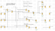
I've got an assignment to make a lifting bridge using LOGOsoft. So after a lot of effort I managed to get a somewhat efficient circuit but I'd like to know what steps are needed to make this into an algebraic equation and minimize it.
The bridge has 4 inputs and 4 outputs:
I1: Raise button (NO)
I2: Lower button (NC)
I3: Is fully raised (NC)
I4: Is fully lowered (NC)
Q1: Warning lights
Q2: Traffic barrier
Q3: Set motors to raise
Q4: Set motors to lower
These are the needed functionalities:
Raise:
Once the raise button (I1) is pressed, wait 2 seconds.
Flash lights (Q1) for 10 seconds (1Hz).
Keep lights (Q1) in and lower barrier (Q2) and wait 5 seconds.
Start motors (Q3) to raise the bridge until fully raised (I3).
Turn motors (Q3) off.
Lower:
Once the lower button (I2) is pressed, wait 2 seconds.
Start motors (Q4) to lower bridge until fully lowered (I4).
Wait 2 seconds and lower barrier (Q2)
Wait 5 seconds and turn off lights (Q1)
First I made a truth table for each output. E.g. the motors can't raise (Q3) the bridge if it's fully raised (I3).
These formulas for each output if I disregard the timers that need to be implemented:
Q1 = ~I4 ^ ~(I1 v I2 v I3)
Q2 = Q1
Q3 = I1 ^ ~(I2 v I3)
Q4 = I2 ^ ~(I1 v I4)
These equations represent the core for my circuit and work as I expect. The problem arises when I implement timers and retentivity. This can be built upon said core but I am clueless on how to represent this in algebra (see attached file: C.zip).
How do I represent my current circuit in algebra? Is it even possible? How do I minimize the circuit if I have the equation?

