Continue to Site

Welcome to our site!

Electro Tech is an online community (with over 170,000 members) who enjoy talking about and building electronic circuits, projects and gadgets. To participate you need to register. Registration is free. Click here to register now.

  • Welcome to our site! Electro Tech is an online community (with over 170,000 members) who enjoy talking about and building electronic circuits, projects and gadgets. To participate you need to register. Registration is free. Click here to register now.

How to repair or replace this micro switch please?

Status
Not open for further replies.

georgesio

New Member
Hi,

I've got a device which monitors the sleep. It's a very tiny one. Unfortunately I broke the microswitch that allows to start it.
I'm a noob in electronics. I think it's not a common on/off switch, here is what it's doing :
- long press : switch on the device
- long press : switch off the device
- short press : toggle between different modes on the LCD screen

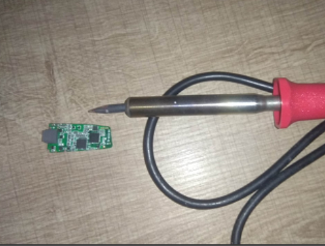
Here is the device (approx 3cm x 1cm)
1.jpg


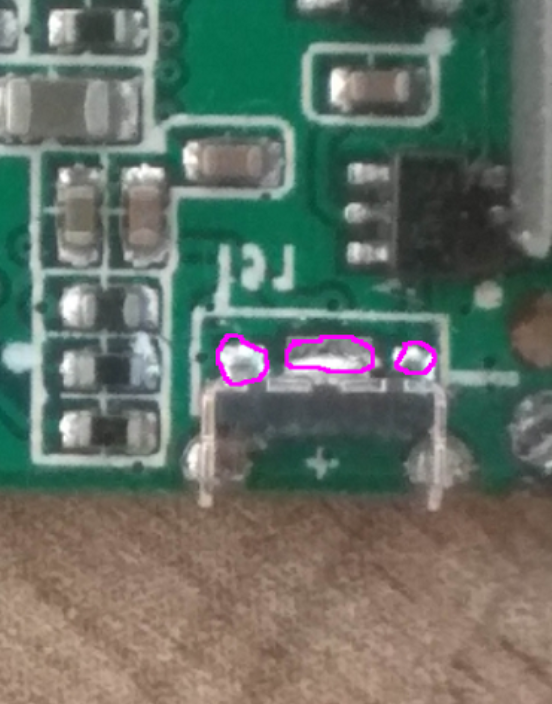
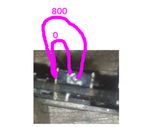
Zooming on the broken switch :

2.jpg


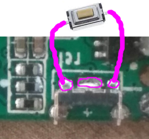
The switch was something like this one (around 2mm):
3.jpg


Currently to start the device I use the tip of a screwdriver to make the contact between the 2 metallic parts (green arrow).
I know I won't be able to replace the switch by a new one because it's too tiny and I don't have any microscope to see what I'm doing (I just have a big soldering iron) so I'd like to find a solution to be able to replace it by another system, even if it's ugly. Like for exemple putting one bigger switch next to the battery... Is it possible?
If you have any idea please share I really like this device and would like to save it from trash.
 
If you can find the correct switch, it would probably be easiest to find someone with a microscope and a small soldering iron, because it's not a difficult job.

The switch itself is just on/off. The long press / short press functions are done by one of the integrated circuits on the board. You only need something that shorts the contacts when you press the button. Disconnecting the battery will stop the device, but it might cause it to lose memory, and when you reconnect, it might not turn on until you press the switch.

In the switch like that there is a metal disc under the button. You can see the pads that it contacts in your picture with the green arrow. The disk is concave so that it only touches the pads around the edge. When the button is pressed, the disk becomes flat and connects to the middle pad, while still touching at least one of the pads around the edge.

If you buy one of the switches, you can just take the top part, the button and the metal disk, and fit it to what is in the photo. The metal part in the photo of the switch is only to keep the button and disk in place when the switch is released, so some glue or a rubber band around the whole board might work for that.
 
It's known as a tactile switch. If you have the ability to solder it should be easy to replace.

Mike.
 
If you can find the correct switch, it would probably be easiest to find someone with a microscope and a small soldering iron, because it's not a difficult job.

The switch itself is just on/off. The long press / short press functions are done by one of the integrated circuits on the board. You only need something that shorts the contacts when you press the button. Disconnecting the battery will stop the device, but it might cause it to lose memory, and when you reconnect, it might not turn on until you press the switch.

In the switch like that there is a metal disc under the button. You can see the pads that it contacts in your picture with the green arrow. The disk is concave so that it only touches the pads around the edge. When the button is pressed, the disk becomes flat and connects to the middle pad, while still touching at least one of the pads around the edge.

If you buy one of the switches, you can just take the top part, the button and the metal disk, and fit it to what is in the photo. The metal part in the photo of the switch is only to keep the button and disk in place when the switch is released, so some glue or a rubber band around the whole board might work for that.

Thanks for your help Diver300.
Yes you described exactly how the switch works. You know what I even not thinked of replacing the top part of the switch by another one without any need to solder! thanks for this suggestion this is indeed the easiest solution.
Let's find this switch, I hope it's not a proprietary one and it can be find as standard parts on ebay/aliexpress


It's known as a tactile switch. If you have the ability to solder it should be easy to replace.

Mike.

Thanks for your help Mike.
Unfortunately I can't solder this tiny part because my iron is too big and even if I had a smaller one the pcb is too small I need a magnifier or a microscope and all the stuff to keep the pcb in place, I don't have this, and moreover Idon't have the skills :)

170f9c7f2e8a8d72313b05eb3c9c1a29.png
 
I found this one, the dimensions seem to be the same (mine were all black, this one is white but maybe it's not important). But I don't see any metallic concave disc/plate at the bottom, the one that should allow the contact. It seems to be plastic, so I don't understand how it can connect the metallic disc with the edges when the button is pressed. Probably not the right switch.

**broken link removed**

Edit :

I've searched the whole ebay and aliexpress and can't find a similar switch with a metallic membrane.

Maybe I can just use a switch like this one, and remove the white connector, and solder the 3 wires to the 3 pads I've circled on the pic below?

2b29a44a2b8542fa6999ecef1f713d49.png


There are also the same switches but with only 2 wires, I don't know the difference.
 
Last edited:
I found this one, the dimensions seem to be the same (mine were all black, this one is white but maybe it's not important). But I don't see any metallic concave disc/plate at the bottom, the one that should allow the contact. It seems to be plastic, so I don't understand how it can connect the metallic disc with the edges when the button is pressed. Probably not the right switch.
The disc is inside the switch, so you won't see it until you open one up. Those would be a good start to either replace the switch, or to open one up and use the button bit on the existing base.
 
Nope there is 3 pads the big one hold the switch frame.
The 2 little ones are the contacts of the switch.
 
Thanks guys :)
So if the middle part is just holding the switch frame, I just have to solder the switch on the left and right pad, right?

I used my multimeter to take some measures, if it can help (I used the diode selector) :


- I tested the left pad against all the others:

d386376f905846c069c3f729902978eb.png


- I tested the right pad with all the others

b040b549a000a3ff23f3ddfa802de78e.png


- I tested the metallic circle and edges inside the switch :


11a920f2212862a3cc423afa3ee389cf.png
 
I found a tactile microswitch that looks like the one that was on the pcb, do you think Ican I solder it like this ?

e6e66f6629efef72560aa65a44b45c6e.png
 
Status
Not open for further replies.

Latest threads

New Articles From Microcontroller Tips

Back
Top