I see why the LM358 might have problems.
--------------------------------
On high frequency generators the ringing of the coax is a big problem, so termination resistors are inside. Also a good generator should with stand a short all day long. Some generators have 50/75/0 ohm options.
From Keysight/Agilent/HP. All of which I worked for.
Why your function generator outputs twice the programmed voltage
The default setting for Agilent function generators is to display the desired voltage as though terminated into a 50 Ohm load. When a high impedance device, such as an oscilloscope is used to measure the output of the function generator, the waveform appears to be twice the voltage set on the display of the oscilloscope.
Some oscilloscopes can change their input impedance from standard high impedance to a 50 Ohm termination. Another solution is to add a 50 Ohm feed through (Agilent part number: 0960-0301) to the end of the BNC cable.
Other common impedances are: 25,
75, 93, 135, 150, and
600 Ohms -Video systems are most often 75 Ohms and many audio systems use a balanced 600 Ohm termination. If not terminating the output of the function generator into a 50 Ohm load, it may be necessary to adjust the output voltage to compensate for the different impedance. For a 50 Ohm source the desired voltage Vmeasured into an impedance R can be calculated as Vmeasured=
V(R/(R+50)), where
V=2*display or Vmeasured=display(2R/(R+50))
The Agilent 33220A and 33250A function generators have the ability to do this calculation for you and directly display the desired voltage. They include a feature that allows the output termination to be set to any impedance from 1 to 10 k Ohm, or infinite. For example if the output termination is set to 75 Ohms and then generator is connected to an oscilloscope with a 75 Ohm termination (or 75 Ohm feed through). The function generator display will match what is displayed on the scope.
----edited----
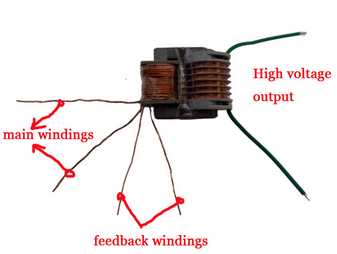
Why should a high voltage transformer be any worse than a 1:1 transformer? or a simple inductor? (is it because of ring)