Continue to Site

Welcome to our site!

Electro Tech is an online community (with over 170,000 members) who enjoy talking about and building electronic circuits, projects and gadgets. To participate you need to register. Registration is free. Click here to register now.

  • Welcome to our site! Electro Tech is an online community (with over 170,000 members) who enjoy talking about and building electronic circuits, projects and gadgets. To participate you need to register. Registration is free. Click here to register now.

How to power this step up transformer with this function generator?

Status
Not open for further replies.

J_Nichols

Member
Hi everyone.
I have this DDS function generator:
aQ05uh.png


Which I have already soldered the components, but I have never switched it on.
Also I have this step up transformer:
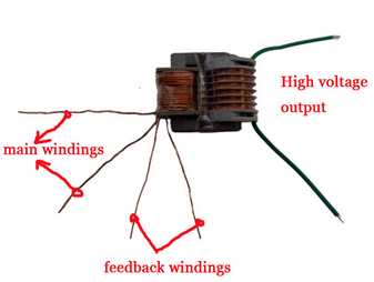
vbjNLB.png


I want to power the transformer using the function generator but I have no idea about where to start.

I will ask some questions, one at a time. The first one is:
Can I power that ferrite transformer using the function generator?

Thank you very much to all who reply.
 
That function generator needs +5, +12 & -12 volts plus ground. You can get all of those from a PC power supply. You need those voltages before you can use it properly.
 
No you can't, don't even try it - it doesn't provide anywhere near enough power, nor is it likely to survive such abuse.

It's a fairly nice little generator, I built one just like it - or it could be two?, I'm not quite sure now :D

It would be a shame to kill it.
 
I want to power the transformer using the function generator
No you can't
Why not? Connect the output of any signal generator to the "main winding". Set the frequency to 10khz to 50khz and see what happens. It will probably make some small high voltage. (very little power)
--edited--
When I make a power transformer (60hz or 250khz) I test it with a signal generator first thing. If the primary is to have 220VAC on the input then I will set the signal generator to 22V or 2.2V and measure the secondary to primary turn ratio. Some times I count wrong. Believe it or not. On high voltage transformers I often sweep the transformer to find the resonant frequency.
 
Last edited:
If you want to protect the generator put a 1k resistor in one of the lines.
Dont connect the high voltage end back to the generator, or Nige's statement will come true.
 
If you want to protect the generator put a 1k resistor in one of the lines.
I don't know how the generator is built but it probably has a 50 ohm resistor inside. (assuming it was designed by an engineer and the intent is to drive a coax cable) I know, too many assumptions.
 
I don't know how the generator is built but it probably has a 50 ohm resistor inside. (assuming it was designed by an engineer and the intent is to drive a coax cable) I know, too many assumptions.

The circuit is freely available, it's a simple AVR based design and a twin LM358 opamp:


Which was why I was pessimistic about driving a high voltage transformer directly from the output of an LM358 (and I MEAN directly - no 50 ohm or anything). Even if it doesn't kill the LM358, you're not going to get any power worth mentioning out of it.
 
a twin LM358 opamp:
119187

I see why the LM358 might have problems.
--------------------------------
On high frequency generators the ringing of the coax is a big problem, so termination resistors are inside. Also a good generator should with stand a short all day long. Some generators have 50/75/0 ohm options.

From Keysight/Agilent/HP. All of which I worked for.

Why your function generator outputs twice the programmed voltage

The default setting for Agilent function generators is to display the desired voltage as though terminated into a 50 Ohm load. When a high impedance device, such as an oscilloscope is used to measure the output of the function generator, the waveform appears to be twice the voltage set on the display of the oscilloscope.
Some oscilloscopes can change their input impedance from standard high impedance to a 50 Ohm termination. Another solution is to add a 50 Ohm feed through (Agilent part number: 0960-0301) to the end of the BNC cable.
Function Generator output impedance diagram

Other common impedances are: 25, 75, 93, 135, 150, and 600 Ohms -Video systems are most often 75 Ohms and many audio systems use a balanced 600 Ohm termination. If not terminating the output of the function generator into a 50 Ohm load, it may be necessary to adjust the output voltage to compensate for the different impedance. For a 50 Ohm source the desired voltage Vmeasured into an impedance R can be calculated as Vmeasured=V(R/(R+50)), where V=2*display or Vmeasured=display(2R/(R+50))
The Agilent 33220A and 33250A function generators have the ability to do this calculation for you and directly display the desired voltage. They include a feature that allows the output termination to be set to any impedance from 1 to 10 k Ohm, or infinite. For example if the output termination is set to 75 Ohms and then generator is connected to an oscilloscope with a 75 Ohm termination (or 75 Ohm feed through). The function generator display will match what is displayed on the scope.
----edited----
Why should a high voltage transformer be any worse than a 1:1 transformer? or a simple inductor? (is it because of ring)
 
Why should a high voltage transformer be any worse than a 1:1 transformer? or a simple inductor? (is it because of ring)

My main concern is ringing, and high voltages blowing the chip. I don't know if a high voltage transformer would be worse or not, but it seems like it should be :D

But regardless, it's not a good idea, and won't do what he appears to be trying to do anyway.
 
No you can't, don't even try it - it doesn't provide anywhere near enough power, nor is it likely to survive such abuse.

It's a fairly nice little generator, I built one just like it - or it could be two?, I'm not quite sure now :D

It would be a shame to kill it.
Thanks,
Do I need to use maybe an audio power amplifier to increase the power of the function generator?
What is the output voltage of such function generator?
 
Thanks,
Do I need to use maybe an audio power amplifier to increase the power of the function generator?
What is the output voltage of such function generator?

The voltage is up towards 24V p-p (due to the +/-12V supply - but the current is very low.

An audio amplifier would increase the power capacity.
 
As Nigel indicates, you do not have the -12v. What you require for that is to take pin 14 of the 24 pin ATX connector and connect it to your -12v pin. You are looking for a blue wire which is next to 3 orange wires at one end.
 
Hi ron,
I dont have one of these, but I do have a few other devices like this, with absolutely no protection.
So I assumed the same also.
 
If your are driving a inductive load, then protection diodes might be a good idea. (Output to supplies) Low capacitance fast diodes. Op-Amps do not like their outputs being driven beyond supply.
Some kind of current limit is good.
If you are going to run fast and use coax cable then termination resistors are good.
Just my thoughts.....
 
As Nigel indicates, you do not have the -12v. What you require for that is to take pin 14 of the 24 pin ATX connector and connect it to your -12v pin. You are looking for a blue wire which is next to 3 orange wires at one end.
Thank you! I am searching for it.
 
Status
Not open for further replies.

Latest threads

New Articles From Microcontroller Tips

Back
Top