Continue to Site

Welcome to our site!

Electro Tech is an online community (with over 170,000 members) who enjoy talking about and building electronic circuits, projects and gadgets. To participate you need to register. Registration is free. Click here to register now.

  • Welcome to our site! Electro Tech is an online community (with over 170,000 members) who enjoy talking about and building electronic circuits, projects and gadgets. To participate you need to register. Registration is free. Click here to register now.

How to parallel two 2N3055 transistors = 120vac, 150 watts?

Status
Not open for further replies.
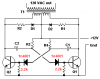
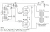
I corrected the horrible original inverter by correcting the polarity of the capacitors, adding series base diodes and adding base-emitter resistors. Decrease the base bias resistors to 47 ohms and increase the capacitor values 4 times the original.
 

Attachments

  • bad inverter corrected.PNG
    bad inverter corrected.PNG
    6.3 KB · Views: 3,306
The transformer inductance determines the magnetizing current, it does not limit the operating (input) current.
That is true if the primary and secondary are well coupled at the frequency of interest. But if the coupling at that frequency is poor, then the inductance can limit the current.

Though maybe I should have said that the inductance would limit the rise time of the current. If the switching frequency is fast, then the current may not get up to a nominal value before the next transition.

And, since we are talking about a square wave, the real frequency of those edges will be much higher than the switching frequency.

Now, I wasn't saying that this IS the problem, Just that it might be. And the first thing that I would do to check would be to look at the current waveform with an o'scope.
 
It took me a while to find this circuit in my stuff, I think this is the circuit that I built.

**broken link removed**
 
It took me a while to find this circuit in my stuff, I think this is the circuit that I built.

**broken link removed**

LOOKS a Little Too SIMPLE.
No Caps to help control the Frequency.
And without the Diodes/Resistors across the Primary's, it will create a lot of Voltage Spikes to damage the transistors.

Did you look at the Links I Posted on 19 and 20.
(Sorry, 20 was a Double Post by mistake.) (Duplicate deleted by Moderator)
Both these circuits do Work.
The C-Mos one is Quite Good.

But Newer Designs are better in as much as the get rid of Big Iron Core Transformer.
But not very practical for Hobbiests!
 
Last edited by a moderator:
Isn't anyone doing any math here? :(

The 2N3055 transistor has a current rating of 15 amps max plus a gain of around 20 - 30 at best.

In my books that says that in ideal conditions you could maybe push ~180 watts to the inverter input but to do so would take somewhere between 500 - 750 ma base drive current. :facepalm:
No.
The hFE or beta is used for a linear amplifier that has plenty of collector to emitter voltage and for the 2N3055 it is a minimum hFE of only 5 when its collector current is 10A and its collector to emitter voltage is at least 4V.

You want the transistors to saturate with a low voltage drop, the datasheet says for a collector current of 10A the minimum base current must be 3.3A, then the saturation voltage loss is "only" 3V.
The maximum output power will be only 10A x (12V-3V)= 90W. The transistors will produce total heating of 30W. The base bias resistors will be 3 ohms and will produce total heating of 33W.
The base emitter junctions of the transistors will produce total heating of 6.6W. VERY poor efficiency.

Gary's circuit with no capacitors has both transistors conducting maybe 500mA each at the same time without oscillation.
 
Hi,

I have seen a lot of inverters made with the 2N3055 transistor and it surprises the heck out of me that anyone would really want to make an inverter with these old transistors. I think they were originally made for use for audio where they had to work in the linear mode so saturation voltage wasnt much of an issue.

In an inverter that runs off of a battery, efficiency is a very important property of the inverter. With a 50 percent efficiency, the battery runs down twice as fast as one with a theoretical 100 percent efficiency. So the goal of high efficiency becomes very apparent.

If it is just for lighting, the best bet is to use products that run directly from 12v DC. Light bulbs are not as good as LED's either, for various reasons besides efficiency. White LEDs work pretty well these days, the high power types. You can get a lot of light from a 10 watt LED, and have it directed in the direction you really need to have lit up rather than over a 360 degree field where a lot of light is lost using an incandescent.

When the lights went out in our state due to hurricane Sandy i was able to keep my LEDs shining for 4 or 5 days 24 hours a day, not problem, and all that from a 12v 7AHr battery. Given a 650AHr battery, i could light up the whole town :=)

The highest efficiency these days comes from using MOSFET designs. MOSFETs drop much less voltage than old type bipolar transistors. So if you really do need an inverter, try to find a design that uses MOSFETs at least. Going from 12v to 120v isnt that easy though, so try to use LEDs that run from 12v and also are efficient (series strings rather than parallel units).
 
Mosfets are better than 2n3055 transistors. Wonder if this circuit will work?

**broken link removed**
 
Mosfets are better than 2n3055 transistors. Wonder if this circuit will work?

**broken link removed**

Hi,

You mean work as an inverter or work as a paper weight? (ha ha)

More seriously, i doubt that the efficiency would be very good even if it does work. Why dont you just try a fifty percent duty cycle oscillator with inverter gate that drives the MOSFETs maybe with a little dead time delay?
 
Gary,
I used to fiddle with this sort of stuff and the design I started with was a self oscillating multivibrator like the one you are showing us.
It used a separate winding to drive the transistor bases. The problem with this design is that the transistors switch only by having the transformer go into saturation. I found a better approach was to use a separate oscillator. I needed a 50Hz supply to run a reel to reel tape recorder at the beach!!.
By designing the transformer to operate at say 45 Hz, you could reduce the magetising currents.
I found that the no load input current due to the transformer going into saturation was a big problem. With the separate oscillator, the frequency stability was good and the efficiency quite good too.
I note many of the comments try to help but actually dont answer your question. If you are an inveterate fiddler, then go for it and use up all your old parts. I too have a box like yours and I even have some Philips OC16 power transistors that have never, and probably will never be used!!.
Mr ALs' post 27 makes a lot of sense, but I can say that the 2N3055 was characterised for switching applications but ideally needs a good base drive arrangement to turn it off quickly in a couple of microseconds. Mr Al does say they were used in inverters.
hope this helps.
 
Here is a very simple squarewave inverter using Mosfets. There is no dead-time so one Mosfet is turning off when the other one is turning on causing a current spike and reduced efficiency.
The CD4047 IC produces a squarewave with exactly 50-50 symmetry.
 

Attachments

  • Mosfets square-wave inverter.PNG
    Mosfets square-wave inverter.PNG
    84.9 KB · Views: 3,298
Hi,

That's something like i was thinking about in post #29. A fifty percent duty osc that drives the MOSFETs.

One way to add some dead time is to use an open collector inverter gate, pullup resistor and cap on the output, followed by a Schmitt Trigger inverter gate, followed by an inverting gate, and put one of these in each gate drive line.
When the osc signal goes high, the cap discharges fast, so the output of the Schmitt Trigger goes high and so the output of the following inverter gate goes low turning off that transistor. When the osc signal goes low, the cap begins to charge but it takes some time to reach the Schmitt Trigger threshold level so there is a delay before the Schmitt Trigger output goes low, and finally when it does the output of the following inverter gate goes high which turns that MOSFET on. So the turn off signal is not delayed while the turn on signal is delayed, and the delay can be adjusted by changing the value of the pullup resistor and capacitor. A small dead time like 1us might be enough if the MOSFETs can turn off fast. For bipolars a longer dead time is better.

The gate and Schmitt Trigger arrangement looks like this:
osc o----INVc---+----INVs-----INV----o gate

and the "+" node has a resistor going to +5v (the pullup) and a cap going to ground:
+5v o-----R-----+-----C-----o GND

and there are two such arrangements, one for each gate:
osc1 o----INVc---+----INVs-----INV----o gate1
osc2 o----INVc---+----INVs-----INV----o gate2

Note "INVc" stands for "Open collector inverter gate" and
"INVs" stands for "Schmitt Trigger inverter gate", and
"INV" is just an inverter gate, although you can use unused Schmitt Trigger inverter gates for this.
Might even be able to use small NPN transistors for the open collector inverter gates, with base resistors.
The gate that follows the resistor and capacitor node must be a Schmitt Trigger type, not a regular gate because the rising capacitor voltage is slow compared to the main switching times.
 
To be honest if a person wants a basic yet decnet driver circuit for any type of inverter Would recomend going out and buying a actual dedicated IC that does the job right. ;)

There are hundreds to choose from and everyone of them will do the job better and with less parts than any toss together circuit made from 555's and logic gate bits N pieces.

I would recomend starting with something like a LM494 or a LM3524 IC or one of their many variants as a basic driver IC and go from there.
I agree. Power designs are so much easier to do with the right part for the job.
 
Status
Not open for further replies.

Latest threads

Back
Top