Continue to Site

Welcome to our site!

Electro Tech is an online community (with over 170,000 members) who enjoy talking about and building electronic circuits, projects and gadgets. To participate you need to register. Registration is free. Click here to register now.

  • Welcome to our site! Electro Tech is an online community (with over 170,000 members) who enjoy talking about and building electronic circuits, projects and gadgets. To participate you need to register. Registration is free. Click here to register now.

How to modulate a 50KHz square, usign a 1kHz triangle pulse

Status
Not open for further replies.

pakachunka

New Member
How can I modulate the amplitude of a 50 kHz square wave form, using a 1 kHz triangle pulse? Can I use a 741 for that?
 
Re: How to modulate a 50KHz square, usign a 1kHz triangle pu

pakachunka said:
How can I modulate the amplitude of a 50 kHz square wave form, using a 1 kHz triangle pulse? Can I use a 741 for that?

You need some kind of VCA ( Voltage Controlled Amplifier ), one way would be to use an FET to make a controlled attenuator - it's often used in AGC and compressor circuits (try a web search). You used to be able to buy specific attenuator I/C's - for volume control and such like, but I think they've been discontinued now.
 
How about using the circuit below?? its works quite easily.

-Ali Sajjad
 

Attachments

  • MOD.jpg
    MOD.jpg
    5.8 KB · Views: 441
Ali Sajjad said:
How about using the circuit below?? its works quite easily.

-Ali Sajjad

That's delightfully simple :) - and should work quite well for a squarewave input - bearing in mind the limitations with the control voltage, because of the 0.7V Vbe drop.
 
Nigel, i am quite impressed with your experience in the field of electronics.. u r very experienced and skilled ( perhaps "skilled" does not suit here)

Would you please explain the reason why this circuit would not be suitable for waves other than sqaure wave? For the nolinear behaviour of a BJT or the distortion encountered at region near the 'C-E' cuttof?

I hope you will clarify..

- Ali Sajjad
 
Ali Sajjad said:
Would you please explain the reason why this circuit would not be suitable for waves other than sqaure wave? For the nolinear behaviour of a BJT or the distortion encountered at region near the 'C-E' cuttof?

To be honest, I'd have to try it to be sure, but with a sinewave (or other slow rising shape) I suspect it would probably distort it at the bottom end, due to operating in a non-linear region. Used with a square wave, essentially as a switched HT supply, it's not going to matter.

One thing I had just forgotten - you wouldn't get a sinewave out at all (I don't think) - the actual input to the circuit is to the base, the collector is just providing a switched HT supply. So a sinewave wouldn't be attenuated through the transistor, it will just provide a varying HT supply, which will be clipped at the voltage on the base - probably :roll:

It's easy enough to test, feed the base from a potentiometer across the supply (no need to bother with a triangle wave for testing), and input a 5V p-p sinewave to the collector - obviously, the sinewave must be positive going only - referenced to 2.5V rather than ground, otherwise it would be rectified.

An interesting little experiment!.
 
If you want to build a true amplitude modulator (analog multiplier), see Fig. 5 in National Semiconductor's **broken link removed**.
 
Thanks

I was thinking on a 2 transistor solution, but Al solution sounds brillant.

Let's see if the transistors agree with him!

I will try, and tell you what I got later.
 
Success! And a lot of noise!

Dear Friends,

I tried something similar to what Ali suggested, but I little bit different, if you understand what I mean!

Check it below!
 

Attachments

  • PowerSupply_153.jpg
    PowerSupply_153.jpg
    17.3 KB · Views: 319
  • PowerSupply_190.jpg
    PowerSupply_190.jpg
    17.3 KB · Views: 353
Complement

By the way,

I forgot to say that the circuit above works, but generates a lot of noise...

But the AM is completely triangle, except for a few glitches on the scope screen, which I don't know if are there because of noise, or because of the trigger of the scope.

Now I will use this to drive a flyback, and try to get a nice 0-3kV ramp... hopefully.
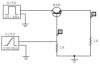
 
It Works!

I put the modulated output of the circuit showed in the primary of a Flyback, and it works!

Thanks for every body!
 
Status
Not open for further replies.

Latest threads

New Articles From Microcontroller Tips

Back
Top