Fluffyboii
Active Member
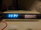
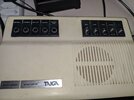
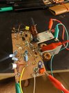
I found this beautiful clock/radio with turquoise vacuum display (it looks more blue on camera). It required the regular cleaning of pots and switches and for some reason someone didn't solder its speaker. Only problem now is that there are no good radios in range here. The antenna of this thing was cut so I soldered a new wire to make it longer but idk how long it should be, at least it gets better signal now. If someone can translate what switches mean it would be nice, for example what AUTO MANUAL or UHR and AUS mean. I pretty much figured the rest.
MW gets some radios with regular fiddling of the radio at 3AM but not as well as my ferrite core antenna radio.
This really made me want to make a simple AM radio and play my own music on it. My school has many powerful transistors in its storage that I can use like bc140, bc160, there are also very overpowered transistors with metal casing that acts like one of the connections. It is really stupid that they got those very expensive BJTs but didn't get any comparators, 555 ICs and other simple stuff that students often need.
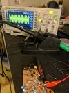
The thing is I accidentally made the required components of an radio for my modular synth with op amps. They wont work at high frequencies but fun to play with for making music. I also have a vague idea of what I need to make one from my analog/digital communication class. I need a pure sine wave fed to a voltage controlled amplifier that is biased with some DC voltage so that it can be demodulated with a simple diode envelope.
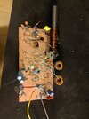
I could probably use a simple op amp amplifier for sound input stage and add a electret mic for fun but I am really in the mood of torturing myself with analog circuit design. I want to make something I can show to my teachers with pride that only consists transistors soldered on a piece of copper like how old electronics predating PCBs were put together.
I was looking at different circuit designs for simple AM radios. Most of them are using base of a BJT to modulate the signal by changing the collector current and a simple RC circuit to determine the operating frequency. Or there are circuits that I don't understand anything about because they are hella complex.
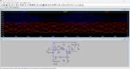
For sound input stage I think I can get away with a simple CS amplifier and a source follower to amplify the input since I don't need to much gain and I don't think inverted signal will prove any problems. The confusing thing is getting a pure sine wave with a fixed frequency. I was thinking of using a quartz crystal but smallest I can get is 2Mhz and even if I use a clock divider I don't think it is wise to use 1Mhz and I should use a less used frequency at the edges of MW radio frequencies. There was a LM13700 triangle to sine shaper circuit I made for an LFO but even though sine wave out of that thing looked nice I don't think it can operate in Mhz range. Looks like I need to use a simple BJT RC oscillator. Single transistor ones seems a bit unreliable so I will need to look into it. I also need to figure out a way to make a transistor VCA. This one is nice but idk how to make it without op amps since its is using one to subtract voltages and it probably doesn't work with negative CV inputs. One way I know to make a multiplier is the simple 2 transformer, 4 diode textbook sample but those transformers are expensive and hard to deal with in audio frequency range and I expect non the less for AM range.

Before jumping to say transmitting radio signals are illegal, I know. As I said there are no AM radios here that can be heard with even the best radio I could find in daytime. At the middle of the night I can find some Russian or Greek radios and thats it. And I also know that doesn't change the fact that this thing can create interference and alarm some authorities. All I want to make a nice transmitter that can be scaled up and doesn't use sketchy techniques to keep part number or complexity low and learn a bit more about radio transmission stuff. I will eventually figure it out myself by checking old radio books and textbooks. I think if I can make something nice it would at least not create unnecessary interference and it is not like I will transmit radio 7/24.
MW gets some radios with regular fiddling of the radio at 3AM but not as well as my ferrite core antenna radio.
This really made me want to make a simple AM radio and play my own music on it. My school has many powerful transistors in its storage that I can use like bc140, bc160, there are also very overpowered transistors with metal casing that acts like one of the connections. It is really stupid that they got those very expensive BJTs but didn't get any comparators, 555 ICs and other simple stuff that students often need.
The thing is I accidentally made the required components of an radio for my modular synth with op amps. They wont work at high frequencies but fun to play with for making music. I also have a vague idea of what I need to make one from my analog/digital communication class. I need a pure sine wave fed to a voltage controlled amplifier that is biased with some DC voltage so that it can be demodulated with a simple diode envelope.
I could probably use a simple op amp amplifier for sound input stage and add a electret mic for fun but I am really in the mood of torturing myself with analog circuit design. I want to make something I can show to my teachers with pride that only consists transistors soldered on a piece of copper like how old electronics predating PCBs were put together.
I was looking at different circuit designs for simple AM radios. Most of them are using base of a BJT to modulate the signal by changing the collector current and a simple RC circuit to determine the operating frequency. Or there are circuits that I don't understand anything about because they are hella complex.
For sound input stage I think I can get away with a simple CS amplifier and a source follower to amplify the input since I don't need to much gain and I don't think inverted signal will prove any problems. The confusing thing is getting a pure sine wave with a fixed frequency. I was thinking of using a quartz crystal but smallest I can get is 2Mhz and even if I use a clock divider I don't think it is wise to use 1Mhz and I should use a less used frequency at the edges of MW radio frequencies. There was a LM13700 triangle to sine shaper circuit I made for an LFO but even though sine wave out of that thing looked nice I don't think it can operate in Mhz range. Looks like I need to use a simple BJT RC oscillator. Single transistor ones seems a bit unreliable so I will need to look into it. I also need to figure out a way to make a transistor VCA. This one is nice but idk how to make it without op amps since its is using one to subtract voltages and it probably doesn't work with negative CV inputs. One way I know to make a multiplier is the simple 2 transformer, 4 diode textbook sample but those transformers are expensive and hard to deal with in audio frequency range and I expect non the less for AM range.
Before jumping to say transmitting radio signals are illegal, I know. As I said there are no AM radios here that can be heard with even the best radio I could find in daytime. At the middle of the night I can find some Russian or Greek radios and thats it. And I also know that doesn't change the fact that this thing can create interference and alarm some authorities. All I want to make a nice transmitter that can be scaled up and doesn't use sketchy techniques to keep part number or complexity low and learn a bit more about radio transmission stuff. I will eventually figure it out myself by checking old radio books and textbooks. I think if I can make something nice it would at least not create unnecessary interference and it is not like I will transmit radio 7/24.
Attachments
Last edited:

