Continue to Site

Welcome to our site!

Electro Tech is an online community (with over 170,000 members) who enjoy talking about and building electronic circuits, projects and gadgets. To participate you need to register. Registration is free. Click here to register now.

  • Welcome to our site! Electro Tech is an online community (with over 170,000 members) who enjoy talking about and building electronic circuits, projects and gadgets. To participate you need to register. Registration is free. Click here to register now.

How to make AM radio transmitter with only BJTs

Status
Not open for further replies.

Fluffyboii

Active Member
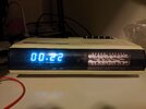
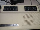
I found this beautiful clock/radio with turquoise vacuum display (it looks more blue on camera). It required the regular cleaning of pots and switches and for some reason someone didn't solder its speaker. Only problem now is that there are no good radios in range here. The antenna of this thing was cut so I soldered a new wire to make it longer but idk how long it should be, at least it gets better signal now. If someone can translate what switches mean it would be nice, for example what AUTO MANUAL or UHR and AUS mean. I pretty much figured the rest.

MW gets some radios with regular fiddling of the radio at 3AM but not as well as my ferrite core antenna radio.
This really made me want to make a simple AM radio and play my own music on it. My school has many powerful transistors in its storage that I can use like bc140, bc160, there are also very overpowered transistors with metal casing that acts like one of the connections. It is really stupid that they got those very expensive BJTs but didn't get any comparators, 555 ICs and other simple stuff that students often need.

The thing is I accidentally made the required components of an radio for my modular synth with op amps. They wont work at high frequencies but fun to play with for making music. I also have a vague idea of what I need to make one from my analog/digital communication class. I need a pure sine wave fed to a voltage controlled amplifier that is biased with some DC voltage so that it can be demodulated with a simple diode envelope.

I could probably use a simple op amp amplifier for sound input stage and add a electret mic for fun but I am really in the mood of torturing myself with analog circuit design. I want to make something I can show to my teachers with pride that only consists transistors soldered on a piece of copper like how old electronics predating PCBs were put together.
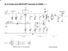
I was looking at different circuit designs for simple AM radios. Most of them are using base of a BJT to modulate the signal by changing the collector current and a simple RC circuit to determine the operating frequency. Or there are circuits that I don't understand anything about because they are hella complex.

For sound input stage I think I can get away with a simple CS amplifier and a source follower to amplify the input since I don't need to much gain and I don't think inverted signal will prove any problems. The confusing thing is getting a pure sine wave with a fixed frequency. I was thinking of using a quartz crystal but smallest I can get is 2Mhz and even if I use a clock divider I don't think it is wise to use 1Mhz and I should use a less used frequency at the edges of MW radio frequencies. There was a LM13700 triangle to sine shaper circuit I made for an LFO but even though sine wave out of that thing looked nice I don't think it can operate in Mhz range. Looks like I need to use a simple BJT RC oscillator. Single transistor ones seems a bit unreliable so I will need to look into it. I also need to figure out a way to make a transistor VCA. This one is nice but idk how to make it without op amps since its is using one to subtract voltages and it probably doesn't work with negative CV inputs. One way I know to make a multiplier is the simple 2 transformer, 4 diode textbook sample but those transformers are expensive and hard to deal with in audio frequency range and I expect non the less for AM range.
1669645629235.png

Before jumping to say transmitting radio signals are illegal, I know. As I said there are no AM radios here that can be heard with even the best radio I could find in daytime. At the middle of the night I can find some Russian or Greek radios and thats it. And I also know that doesn't change the fact that this thing can create interference and alarm some authorities. All I want to make a nice transmitter that can be scaled up and doesn't use sketchy techniques to keep part number or complexity low and learn a bit more about radio transmission stuff. I will eventually figure it out myself by checking old radio books and textbooks. I think if I can make something nice it would at least not create unnecessary interference and it is not like I will transmit radio 7/24.
 

Attachments

  • IMG_20221128_002239.jpg
    IMG_20221128_002239.jpg
    387.6 KB · Views: 194
  • IMG_20221128_003026.jpg
    IMG_20221128_003026.jpg
    499.6 KB · Views: 193
Last edited:
Also, the values in the second one are for short wave bands, not medium wave; the inductor values would need recalculating. I included that as an example of simple modulation.
I found the way the modulator was drawn quite confusing :D

One of those situation where you would rotate a paper circuit in your hands :D
 
For a transmitter you NEED!!! a transformer, or at least wound coils for tuned circuits - the first of those two examples is truly horrible, and would cause massive interference all over the RF spectrum - and appears to be designed to do just that.

Just as a receiver needs tuned cicuits, so does a transmitter.
Yes I need inductors in these circuits for sure. But making a transformer with specific ratios, turns and bandwidth issues and other random stuff happened with my other multiplier circuit makes me not want to do the multiplying with a transformer but with solid state devices even tho it would increase the amount of BJTs used considerably. The tank circuit and such can have their inductors.
 
Yes I need inductors in these circuits for sure. But making a transformer with specific ratios, turns and bandwidth issues and other random stuff happened with my other multiplier circuit makes me not want to do the multiplying with a transformer but with solid state devices even tho it would increase the amount of BJTs used considerably. The tank circuit and such can have their inductors.
RF transformers are pretty simply to wind - no different to winding a tank coil etc. (basically just a smaller winding over a tank coil).

The transformer in question simply matches the impedance of the transistor to that of the aerial.
 
RF transformers are pretty simply to wind - no different to winding a tank coil etc. (basically just a smaller winding over a tank coil).

The transformer in question simply matches the impedance of the transistor to that of the aerial.
Is it possible to replace it with a common collector stage to have same results. Just curious.
 
Is it possible to replace it with a common collector stage to have same results. Just curious.
No.

Tuned circuits are resonant and can have the effect of increasing the wanted signal while at the same time attenuating off-frequency noise.

(Think of it like pushing a swing - as long as the pushes are at the correct time, the amplitude of the swing movement is a lot more than the amplitude of the push. The same force applied at random intervals just makes it wobble about a bit, there is no resonance).
 
I agree with Nigel Goodwin , you really should have both a fairly clean oscillator and an LC filter on the output such as in the original Wenzel schematic in post #11 so you don't have significant out-of-band emissions. Charles Wenzel knows his stuff and I would not try to second guess his work or cheapen it.
 
There is the oscillator from #11. I know electronic gods make RF circuits on copper for less parasitics and better performance but when I look at their solder jobs I notice, more stuff than what I did here is soldered to copper itself. I wonder if they are using the cooper as VDD instead of GND. That would explain the lack of connections to copper in my circuit. I will check if this oscillates tomorrow with schools oscilloscope. My mini ones power adapter is lost right now.
 

Attachments

  • IMG_20221204_190257.jpg
    IMG_20221204_190257.jpg
    1.1 MB · Views: 138
I agree with Nigel Goodwin , you really should have both a fairly clean oscillator and an LC filter on the output such as in the original Wenzel schematic in post #11 so you don't have significant out-of-band emissions. Charles Wenzel knows his stuff and I would not try to second guess his work or cheapen it.
Not trying the cheapen anything. I am aware of that a mere mortal like me can never dream of designing a circuit that operates in RF range. Just trying to understand how it works so I can maybe modify it for my needs in the future.
 
I tried the oscillator from #11 circuit. As I expected it did not work. After checking everything I decided to use another BJT. It did not work in the same way. I get this weird noise with peaks. I tried changing crystal with different values and nothing change. Should I start by trying different capacitor values or mess with bias votlages.
 

Attachments

  • IMG_20221205_122218.jpg
    IMG_20221205_122218.jpg
    1.1 MB · Views: 152
  • IMG_20221205_122214.jpg
    IMG_20221205_122214.jpg
    1.1 MB · Views: 146
  • IMG_20221205_122138.jpg
    IMG_20221205_122138.jpg
    7.2 MB · Views: 155
The upper circuit in post 18 uses a Colpitts oscillator, one of the most reliable and uncritical types.

What crystals have you tried using?
 
Regular quartz cystals. 1Mhz.
The component in a the yellow package isn't a regular AT-cut crystal.

The AT-cut crystals are usually quite easy to get to oscillate. However, at low frequencies they end up quite thick. They work best if the diameter or length is a lot larger than the thickness, as they oscillate in the middle, and not at the edges.

An AT-cut 1 MHz crystal is 1.6 mm thick, so it's going to be around 10 mm or more in the other dimensions.

The lowest frequency AT-cut quartz crystals appear to be 1.8432 MHz,

Quartz crystals below about 500 kHz are usually tuning-fork crystals, which are very different.

What you've got there is a ceramic resonator, which is cheaper than a crystal and can be smaller at lower frequencies but is harder to make oscillate. They are not as accurate either. I've only seen ceramic resonators used in Pierce oscillators.
Oh I see. I wasn't sure of 1.8Mhz since some AM radios can't receive it. But I tried with AT-cut one too, metal cased one. But in my school we got 4Mhz and higher. Maybe I should look at a 1Mhz crystal circuit. I also purchased some adjustable cspacitors so I can make a variable LC oscillator.
 
Got this working. I assume 700Khz is bit too low so maybe I should remove some turns.

Also found this small transformer, maybe it can be used for multipication.
 

Attachments

  • IMG_20221205_161553.jpg
    IMG_20221205_161553.jpg
    1.4 MB · Views: 146
  • IMG_20221205_161558.jpg
    IMG_20221205_161558.jpg
    7.3 MB · Views: 152
  • IMG_20221205_161644.jpg
    IMG_20221205_161644.jpg
    766 KB · Views: 151
Got this working.
Good.

I assume 700Khz is bit too low so maybe I should remove some turns.
Fewer turns will lower the inductance, and so increase the oscillator frequency.

Also found this small transformer, maybe it can be used for multipication.
I am not sure what you mean by "multiplication".
I would not use that "transformer", it looks like a common mode choke for mains noise suppression, and is probably less that desirable to use in an oscillator.

JimB
 
Good.


Fewer turns will lower the inductance, and so increase the oscillator frequency.


I am not sure what you mean by "multiplication".
I would not use that "transformer", it looks like a common mode choke for mains noise suppression, and is probably less that desirable to use in an oscillator.

JimB
Took few turns of the coil and get it around 800Khz which is fine for me. I have 60pF variable capacitors but adding those wouldn't give me a meaningful change in frequency anyway.
The multiplication I meant was the transformer in this circuit. I mean in order to amplitude modulation to work I need to make a modulator which is a multiplier in this case I assumed.
The voltage output quite high should I do something about it. And that doesn't really look like a good sine wave, I think it is good enough but it must create a lot of mathematical mess at the output. God knows what is the inverse Fourier transform of that.
 

Attachments

  • IMG_20221205_164527.jpg
    IMG_20221205_164527.jpg
    98.2 KB · Views: 142
  • IMG_20221205_164007.jpg
    IMG_20221205_164007.jpg
    7.7 MB · Views: 161
Last edited:
Took few turns of the coil and get it around 800Khz which is fine for me. I have 60pF variable capacitors but adding those wouldn't give me a meaningful change in frequency anyway.

800KHz looks pretty low for the small number of turns you have?.

The multiplication I meant was the transformer in this circuit. I mean in order to amplitude modulation to work I need to make a modulator which is a multiplier in this case I assumed.

No, an AM modulator is a modulator - you're confusing everyone (and yourself) by talking about multipliers, which are an entirely different thing in RF. FYI a 'multiplier' is used to multiple the frequency, and is usually just an amplifier and tuned circuit - a classic example would be a 144MHz transmitter, where you woulkd use a 12MHz crystal, then a multiplier stage to multiply by four (to make 48MHz) then a second multiply by three stage to give your 144MHz output

The voltage output quite high should I do something about it. And that doesn't really look like a good sine wave, I think it is good enough but it must create a lot of mathematical mess at the output. God knows what is the inverse Fourier transform of that.

That's why you NEED tuned circuits and filtering.
 
800KHz looks pretty low for the small number of turns you have?.
At first sight I would agree.
But, that ferrite rod looks quite thick and, we do not know the permeability.
So the frequency could be quite OK.


No, an AM modulator is a modulator - you're confusing everyone (and yourself) by talking about multipliers, which are an entirely different thing in RF.
I see where you are coming from with the frequency multipliers, your confusion is understandable.

But mathematically, modulation is a multiplicative process.
I think that Fluffy may be suffering from an overdose of theory, but he is taking practical steps to overcome that.

Coming back to Fluffys question about the toroid coil, I think that he would be best putting it to one side and not using it in this oscillator/modulator project.

The multiplication I meant was the transformer in this circuit.
Fluffy, please stop posting different circuits, the one that you have just posted is intended for use at 25 to 30 MHz, a lot different from 1MHz.
Chopping and changing only creates confusion.

that doesn't really look like a good sine wave,
Correct, it is ugly and full of harmonics.
But as long as you do not connect it to a big long antenna, you will be OK.

The voltage output quite high should I do something about it.
You could put an attenuator on the output.
But first, please show us what circuit you are actually using now for this oscillator.

JimB
 
800KHz looks pretty low for the small number of turns you have?.


No, an AM modulator is a modulator - you're confusing everyone (and yourself) by talking about multipliers, which are an entirely different thing in RF. FYI a 'multiplier' is used to multiple the frequency, and is usually just an amplifier and tuned circuit - a classic example would be a 144MHz transmitter, where you woulkd use a 12MHz crystal, then a multiplier stage to multiply by four (to make 48MHz) then a second multiply by three stage to give your 144MHz output


That's why you NEED tuned circuits and filtering.
I see. One method of obtaining AM was multiplying the message signal + some DC bias with cos(2pi*carrier freq). I thought the way these simple AM transmitters were working was using transistors to do that. Like the modulator I did build a while ago which does output an amplitude modulated signal:
1670253252424.png

You could put an attenuator on the output.
But first, please show us what circuit you are actually using now for this oscillator.
1670253462936.png

This was the circuit but I used 1nF capacitors instead 680nF so it explains the longer wavelength. Ferrite rod had around 12mm radius and online calculator told me I needed around 28 turns of this 0.88mm wire for 70uH and I went bit more than that (31) so I think it is normal.
 
Last edited:
Coming back to Fluffys question about the toroid coil, I think that he would be best putting it to one side and not using it in this oscillator/modulator project.
I thought that toroid was probably useless for this use case but wanted to ask non the less. I got another toroid with lot more turns which shows up as 25mH on my test device which is most likely useless as well. I got some resistor like packade inductors that maybe can be used for filtering. I did not test the ferrite stick one because I was at the lab and did not had my tester with me but I can test that one to see what is the actual inductance of it.

I knew the crystal circuit was meant to be used with high frequency crystals, probably capacitor values were too high to be used with low freq crystals so I did not bother too much to fix it after it did not work on second test and went with the Colpitts oscillator instead. Colpitts oscillator has less distorted output when measured from the base but I leaned that using that requires buffering since it can not supply current from there.
 
Last edited:
Status
Not open for further replies.

Latest threads

New Articles From Microcontroller Tips

Back
Top