Continue to Site

Welcome to our site!

Electro Tech is an online community (with over 170,000 members) who enjoy talking about and building electronic circuits, projects and gadgets. To participate you need to register. Registration is free. Click here to register now.

  • Welcome to our site! Electro Tech is an online community (with over 170,000 members) who enjoy talking about and building electronic circuits, projects and gadgets. To participate you need to register. Registration is free. Click here to register now.

How to make alogrith for a artificial intelligence line follower.

Status
Not open for further replies.
I could help you if you answer my questions and if you post a circuit diagram.
 
I could help you if you answer my questions and if you post a circuit diagram.

Thanks..!!

But now chip is working correct as i want...
pls tell should i connect fly back diode or no with capacitor..
b'coz i am using small motor and i don't want to large my circuit any more..!!
the schematic of my 298 is as per data sheet....

and please tell i want to connect uC which work on 3.3V so how to connect 298 chip which logic supply is in between 5 to 7V..???
 
Google "3.3 volt H bridge driver chip"

OK, i will try to handle this h bridges section.....

Pls suggest me on this:-

SO, working with LDR for line follower is creating a problem while testing:-
1.) the response time was very less..
2.) I can't check properly which ldr is working due to light interface..!!
as i am using 100K variable resistance at 26-27Kohms ...........

Pls tell should i continue with LDR or just have IR led?? and if IR then which IR receiver diode one or TSOP 1738 one ( wires)
 
Use IR, LDR is to dependent on ambent light and will need to be reajusted all the time, it is also slow.

google "IR line follower"
 
Last edited:
But IR led switching at 38Khz........but here it is not used why???
 

Attachments

  • 12222.jpg
    12222.jpg
    9.3 KB · Views: 311
OK, I was testing my circuit using multimeter......it is working fine with it.
But testing with uC( quick start board) the output is not working well.....I have have tested my code with DIP switch in place of sensor output all code are right i don't know what problem in it........
 

Attachments

  • 1222.JPG
    1222.JPG
    43 KB · Views: 314
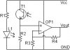
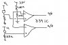
The LM339 runs off of 5 volts, you need a LMV339 to work off 3.3 volts.
from Nationals site;
"The LMV393 and LMV339 are low voltage (2.7-5V) versions of the dual and quad comparators, LM393/339, which are specified at 5-30V."
What IR sensors are you using?
You may need pull ups on the outputs of the opamps.
 
OK, i will do this today.........!!
and pls suggest as you can see arena how to code uC ( only logic).
 
Status
Not open for further replies.

Latest threads

Back
Top