Continue to Site

Welcome to our site!

Electro Tech is an online community (with over 170,000 members) who enjoy talking about and building electronic circuits, projects and gadgets. To participate you need to register. Registration is free. Click here to register now.

  • Welcome to our site! Electro Tech is an online community (with over 170,000 members) who enjoy talking about and building electronic circuits, projects and gadgets. To participate you need to register. Registration is free. Click here to register now.

How to make a 2 second timer

Status
Not open for further replies.

stuhagen

Member
I want to make my 20 year old car do a Tach needle sweep you see in new cars. I have made a Freq generator that outputs exactly 8k rpms.
I just need to have a relay switch this feed with key on, but I am struggling with how to have it go off in just a few seconds to go back to normal operation.
Wasn't sure if a typical R/C circuit would dissipate evenly or quickly.

Goal is to turn car to Ing-'on', tach then sweeps from 0 rpms to 8,000 rpms then back to '0'. I have not physically timed this, but I am guessing 2 seconds it takes to go from 0-8,000-0. I can time it and adjust accordingly. So the time needed is really to get it to the 8000rpm mark, then the power can be removed so it can drop back down to 0 rpms

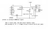
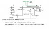
Any recommendations of what to use would be very helpful. I have started a simple schematic attached.

Stu
 

Attachments

  • Needle Sweep.jpg
    Needle Sweep.jpg
    58.9 KB · Views: 409
What frequency is it and does the tach slew at the desired rate?
 
The tach needle "sweeps" when frequency is applied and is rather fast...Albeit I have not timed it. It snaps back faster once frequency signal is removed, and just a hair slower on the rise to 10K.
10K RPMSs = 500HZ. Every 100 RPMs = 5HZ So at 8K RPMs I am at 400HZ. I already have a pre-made HZ generator set static (by resistance) to 8K or 400HZ. So once there is power (12v) to the frequency generator it will immediate sweep the tach needle to 8k RPMs. Once power is removed it will snap back to '0'. So I need to have 12v power to the Frq. Generator just for a few seconds.
 
With a VCO one can use an analog time constant of 1 second towards 500Hz but only reach 400Hz in 2 seconds

Then the sequence would be
T+0 power on and turn on control voltage with RC analog delay to VCO
T+2 Turn off Control Voltage with RC analog delay
T+4 turn off power.
CD4020 or 4060 can be used to create a slow digital clock then a gate to stop the sequence.

As much as I understand your product(s)...I do not understand how to assemble what your quoting. Is there something on the market as a discrete IC that I can use for this? I assume there are a lot of circuits for this Oscillator in conjunction with a Binary counter, but my engineering background is quite antiquated...Have a circuit diagram you can share???

Does "T" + time?
 
LM555 can be reset by grounding pin 4 it need p+ to operate so get another lm555 use as one shot 2 sec monostable. That should do it.
also pin 5 if drugged montarily to gnd will do it. A capacitor f/b from the relay can be used and of course set up your timer .639 rc
 
Last edited:
I still am not quite sure how to design this to go off in 2 sec. Can you give me a circuit design? Here is the 555 timer I have made that produces a static square wave output of 400HZ (= 8000rpms). I may change it to output 10K...not sure yet.

So If I can make this circuit shut down after 2 seconds, that would work I am sure.

Stu
 

Attachments

  • 555 set to 8k.asc
    2 KB · Views: 290
If you are familiar with CMOS, it would help
https://www.fairchildsemi.com/datasheets/CD/CD4060BC.pdf
This old chip has an RC oscillator type built in with a 14 stage binary counter , which means you can use an external or the internal clock set by a RC values to anything you want and use AND OR Gates to combine outputs to create a delayed pulse after With multiple pulses. https://www.elprocus.com/5-different-timer-circuits/

There is also the CD4017 decade counter which allows you use any clock like a 1 Hz clock then sequence events for 1 second at a time with 10 outputs going high sequentially.

A Google "Images" search for CD 4017 schematics will give you some ideas.


The variable frequency clock or VCO would be the next improvement if you are up to this so far.
This can be done as suggested already with a voltage controlled one-shot.. Just someone needs the time to put it all together for you...

There are some extra details you need to define.
Power up by detecting engine start? or just ignition power
Slow ramp ? or just as is with fast start and quick stop?
Does Tach get disabled ? or does it revert to normal operation?
 
Last edited:
If you are familiar with CMOS, it would help
https://www.fairchildsemi.com/datasheets/CD/CD4060BC.pdf
This old chip has an RC oscillator type built in with a 14 stage binary counter , which means you can use an external or the internal clock set by a RC values to anything you want and use AND OR Gates to combine outputs to create a delayed pulse after With multiple pulses. https://www.elprocus.com/5-different-timer-circuits/

There is also the CD4017 decade counter which allows you use any clock like a 1 Hz clock then sequence events for 1 second at a time with 10 outputs going high sequentially.

A Google "Images" search for CD 4017 schematics will give you some ideas.


The variable frequency clock or VCO would be the next improvement if you are up to this so far.
This can be done as suggested already with a voltage controlled one-shot.. Just someone needs the time to put it all together for you...

There are some extra details you need to define.
Power up by detecting engine start? or just ignition power
Slow ramp ? or just as is with fast start and quick stop?
Does Tach get disabled ? or does it revert to normal operation?

The instruments goes hot on "ign on" and stays on through cranking. The tach signal "feed" would be cut and looped to the 10k input signal, then back to normal operation after 2 seconds. I suspect with the 10K tach feed from my 555 with be pretty snappy.
This drawing isn't totally correct as I am not quite sure where to interject the timing circuit. It does need to go off at the relay otherwise the relay will not go back to N/C.

Are you stating that I can use the CD4060 for the square wave generator AND the timer all in one chip?
 

Attachments

  • Needle Sweep.jpg
    Needle Sweep.jpg
    63.3 KB · Views: 317
The instruments goes hot on "ign on" and stays on through cranking. The tach signal "feed" would be cut and looped to the 10k input signal, then back to normal operation after 2 seconds. I suspect with the 10K tach feed from my 555 with be pretty snappy.
This drawing isn't totally correct as I am not quite sure where to interject the timing circuit. It does need to go off at the relay otherwise the relay will not go back to N/C.

Are you stating that I can use the CD4060 for the square wave generator AND the timer all in one chip?
Yes but from your experience with CMOS, I think it will be simpler for you to use one shot timers using the parts you know how to use like a **broken link removed** using many different RC values
  • one for 400 or 500Hz
  • one for timer 1 (monostable or 1shot) of 2seconds for up then disable 500Hz
  • one for timer 2 for 3 or 4 seconds to switch from internal to external pulse Tach signal then off after timer2, **broken link removed**

how does that sound?
 
I can probably work with this. I just need to find out what pins and RC values to use for the delay portion. I read up on the 555 timer website on various uses, but could not find one that does this few second timer thing.

So I could go buy a dual or quad 555 and have it be both the frequency generator AND shut off timer...sounds interesting. And possibly simpler.
 
Can you read the specs that I linked and figure out the RC values?
 
Yes and no. I was having a hard time coming up with there example...That and it was based on the other chip...not the 555. Are you referring to this explanation?

Latching the IC
CD 4060 based timer can be latched to block the oscillation and to keep the output high until resetting. For this IN4148 diode can be used. When the high output is connected to Pin11 through the diode, the clocking will be inhibited when that output becomes high. The IC will stars oscillation again only if it is reset by switching off the power.

Formulae for the Timing Cycle

Time t = 2 n / f osc = Seconds

n is the selected Q output number

2 n = Q output number = 2 x Q no times Eg. Q3 output = 2x2x2 = 8

f osc = 1 / 2.5 (R1XC1) = in Hertz

R1 is the resistance at pin 10 in Ohms and C1, the capacitor at pin 9 in Farads.

For example if R1 is 1M and C1 0.22 the basic frequency f osc is

1 / 2.5(1,000,000 x 0.000,000 22) = 1.8 Hz

If the selected output is Q3 then 2 n is 2 x 2 x 2 = 8

Therefore time period (in seconds) is t = 2 n / 1.8 Hz = 8 / 1.8 = 4.4 seconds
 
long duration timers are easy with the 4060 as it is a digital binary counter, but it needs more work with gates.

No in my question in #12 I was referring to my previous comment in #10 on the quad 555, which supports down to 0.1Hz ( but requires special low leakage big caps and big R. I also requires a 12V LDO regulator as 14,.2V exceeds the max.
 
OK I see....but really...do I need to have more than timer 1? Unless timer 2 is used to shut down tach signal. Ugh....30 years since I graduated in EE and lots of this is becoming Greek...time to bone up I guess.
 
Status
Not open for further replies.

Latest threads

Back
Top