Continue to Site

Welcome to our site!

Electro Tech is an online community (with over 170,000 members) who enjoy talking about and building electronic circuits, projects and gadgets. To participate you need to register. Registration is free. Click here to register now.

  • Welcome to our site! Electro Tech is an online community (with over 170,000 members) who enjoy talking about and building electronic circuits, projects and gadgets. To participate you need to register. Registration is free. Click here to register now.

How to isolate and to pass voltage signal between two isolated circuits.

Status
Not open for further replies.

DX400

New Member
Hi,

What is the best (and quite simple and not very expensive) way to isolate circuit1 from circuit3 by some buffer2?
The circuit1 is some voltage source with some load. The voltage on load might vary from 0.1 to 1 V, and the maximal current on load - up to 30 mA.
The circuit3 is some ADC input of the PC controlled board to measure the load voltage.

CircuitMeasure.jpg


I have to “connect” the load to the ADC input to measure the load voltage, but I am unable to physically connect it. So I need some buffer circuit “2” based, may be, on optocoupler or galvanic (coil) to pass the voltage signal (current no matter) from the load to the ADC input. So the passed through “2”signal have to be equal or proportional to the voltage on load.

I have looked for the optical isolation by some optocoupler, but I haven’t found the suitable example of such circuit.

Give me, please some example(or reference) of the circuit to resolve my problem.
 
Probably one of the easiest ways is to move the ADC to the primary side, using a small 8 pin PIC, then use that to read the analogue value, and send serial data through an opto-isolator.

You can get analogue opto-isolators, but you would probably need to amplify the signal first as it's so small, and I don't think they are terribly linear?.
 
As suggested by Nigel, an 8 pin pic could work well. What resolution do you need for the ADC?

Another possible solution would be a voltage to frequency converter feeding the opto. Again, what resolution is required?

Mike.
 
Thank you very much for the answers.

The ADC resolution should be of 12 bit. What is “8 pin PIC”? It’s some kind of microcontroller?

Please explain how the PIC microcontroller can help here. Or give me some reference if such solution exists.
 
An 8 pin pic is a microcontroller with a 10 bit ADC. Requiring 12 bits is going to make it more difficult. On a 1V signal 1 bit will equal approximately 0.25mV. Do you really need such prescision?

Mike.
 
Last edited:
An 8 pin pic is a microcontroller with a 10 bit ADC. Requiring 12 bits is going to make it more difficult. On a 1V signal 1 bit will equal -025mV. Do you really need such prescision?
No I don't, the 10 bit resolution is enough. Please explain how to use 10 bit ADC PIC microcontroller here.
 
No I don't, the 10 bit resolution is enough. Please explain how to use 10 bit ADC PIC microcontroller here.

As with any micro-controller, you have to program it for it to do anything, but it's pretty easy to read the ADC and send the data out as an RS232 type serial data stream
 
You can get ic's made for the job, but not neccessarily cheap.
You could use the voltage to control the amplitude of a certain frequency, then pass that through a transfomer and detect it again afterwards.
 
There are quite a few integrated current sense plus isolation ICs.

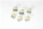
This is a good example:


All you need is a 5V reg from the 24V supply at the load sense side and you get the sense voltage from a totally isolated set of pins at the other side of the IC - with anything up to 500V or more difference between the sides.
 
And you can get Dc current 'transformers'.
 
Perhaps a bit ghetto, but incandescent lamp optically coupled to a CDS (light dependent resistor) cell?

Oh 1/10 Volt. Maybe not.
 
Status
Not open for further replies.

Latest threads

New Articles From Microcontroller Tips

Back
Top