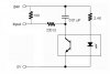
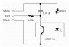
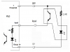
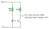
I got stuck on my science project. I used an QTI sensor to give signal to my Pansonic PLC. My PLC can only sense 24 volt signals. I have replaced the resistor for the IR emmiter on the sensor to a 2.4K resistor. However, I found that the output current of the sensor is only 2.5mA, too small for the PLC to sense (the PLC senses 0.1A). I was wondering if there is any other way to increase the output current other than using transistors. Thank you very much in advance.
Continue to Site
")