Continue to Site

Welcome to our site!

Electro Tech is an online community (with over 170,000 members) who enjoy talking about and building electronic circuits, projects and gadgets. To participate you need to register. Registration is free. Click here to register now.

  • Welcome to our site! Electro Tech is an online community (with over 170,000 members) who enjoy talking about and building electronic circuits, projects and gadgets. To participate you need to register. Registration is free. Click here to register now.

How to get common ground from a transformer with 2 outputs

Status
Not open for further replies.

polashd

Member
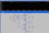
I made a psu using a center tape transformer. It has two output circuits for different voltages. One input of both the circuits is a common end of the transformer, similar to the schematic attached (just to show the connection). I want to supply both the voltage to different part of one project. (like 5v to the MCU and 12v to operational part, motor etc.). To make this happen there should be one common ground (or negative). But I found big voltage between negatives’ of the circuits (rectified negative of 5v and rectified negative of 12v). As both has a common input wire from the transformer, and I will have a common ground.
  • Why both negatives’ are of different level (voltage)?
  • What should I do to get a common ground?
  • Why in the graph one output(dc2) is stable and the other (dc1) is not (dc3 is negative of dc1)?
Transformer 2 output b.jpg
 

Attachments

  • Transformer 2 output b.jpg
    Transformer 2 output b.jpg
    146.5 KB · Views: 212
dc2 is grounded so it's stable when measuring relative to ground.

dc1 is not stable when measuring relative to ground because dc3 is not connected to ground and is flip flopping with the AC wave between transformer terminals. This is a measurement issue, not a circuit issue. Think about what each voltage is being measured against.

The way you did it, I'm not sure you can get common ground unless you go with half wave rectified for one of the rectifiers.
 
Last edited:
Why both negatives’ are of different level (voltage)?
You just cannot connect the circuit like that with two separate bridge rectifiers.
It just does not work.
This is a common mistake.

What should I do to get a common ground?
If you want to use bridge rectifiers, you will need to use a transformer with two separate windings.

Or, you could do something like this:

Dual Voltage PSU.png


By using a 12-0-12v transformer

You can get two DC outputs of 12 and 24 volts (actually it is 1.4 x 12v and 1.4 x 24v due to the peak voltage).

JimB
 
Note that the 12V output of Jim's circuit needs a filter capacitor (like C1) to get low-ripple DC.

That circuit works by having the 24V output use the four diodes as a bridge rectifier, and the 12V output using D3 and D4 as a full-wave rectifier.
 
Note that the 12V output of Jim's circuit needs a filter capacitor (like C1) to get low-ripple DC.
Yes of course, my omission.
Thank you for the correction.

JimB
 
Status
Not open for further replies.

Latest threads

New Articles From Microcontroller Tips

Back
Top