In a sense this question is related to an earlier thread about spot welders, but it is sufficiently different that I thought a new thread was justified. In brief, I now have an operating system for charging the capacitor(s) for a capacitor discharge spot welder. I am now looking on the firing circuit for the SCR. I am planning to use a Semikron SKKT92 with a 2000 A pulse rating. The main reason to chose this device was its big screw connections, and it was cheap ($2 USD each for three) on ebay.
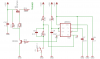
I searched on SCR firing, triggering, and related key words and didn’t get much in the way of explanation, just lots of examples. The datasheet gives what’s required, but not how to get it. Something in my gut tells me that just switching a 12V power supply to the gate manually and momentarily is not the best way to go. Some of the Linear Technology circuits for switching regulators reminded me of circuits used for CDI, so I went down that path and now have two versions that work on the bench (see attachments).
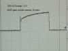
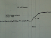
Version A is the simplest and is pretty close to manual, except the turn off is controlled by the capacitor, not my poor reflexes. Version B is a little more complex and most similar to the CDIs with which I am familiar. When I monitor gate potential on my scope, Ver. A gives a good pulse but a long and gradual decay. Ver. B gives a very sharp pulse and fast decay, except one also sees negative spikes (ringing?). In both circuits, I added a resistor (R8 and R3, respectively) on the premiss that it would bleed off unwanted accumulation of charge and possibly prevent false firing.
Bench tests were done with only a 2200 ufd capacitor across the anode and cathode of the SCR at 12V. I suspect that when this is scaled up to the welder size (0.4 to 1.0 F) differences that weren’t apparent on the bench may become VERY apparent.") I want to avoid or at least reduce the likelihood of something becoming too apparent for a brief millisecond.
I want to avoid or at least reduce the likelihood of something becoming too apparent for a brief millisecond.
My specific question are:
1) Is there anything wrong and what are the problems, if any, with simply firing the SCR with a relay?
2) Is the shorter pulse of Ver. B an advantage over the longer decay of the pulse from Ver. B?
3) Are negative spikes bad, or do they help close the gate?
4) What steps can be taken to reduce the ringing, while still retaining the negative pulse?
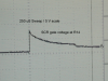
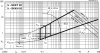
5) The datasheet shows (attached) a best trigger zone (BSZ) that seems to show that at lower voltages (0.5 to 1.3V), lower currents should be used, and one should not exceed 20V through a 20 ohm resistor. My experiments with firing at 9V vs. 12V showed that the former would not reliably trigger; whereas, the latter never failed to trigger. These tests were done using Ver B. Is there a recommended practice for choosing the trigger voltage for these devices, perhaps related to the anode voltage?
6) Will the bleed resistor (R8 and R3, see above) help or is it foolish?
This project is for getting clean tack welds on SS hypodermic tubing, so I can then use brazing for cluster joints in a large model airplane.
Thank you for any help and advice. Unfortunately, this post suffers from wordiness, but maybe that offsets “please help me” post with no other information. John
I searched on SCR firing, triggering, and related key words and didn’t get much in the way of explanation, just lots of examples. The datasheet gives what’s required, but not how to get it. Something in my gut tells me that just switching a 12V power supply to the gate manually and momentarily is not the best way to go. Some of the Linear Technology circuits for switching regulators reminded me of circuits used for CDI, so I went down that path and now have two versions that work on the bench (see attachments).
Version A is the simplest and is pretty close to manual, except the turn off is controlled by the capacitor, not my poor reflexes. Version B is a little more complex and most similar to the CDIs with which I am familiar. When I monitor gate potential on my scope, Ver. A gives a good pulse but a long and gradual decay. Ver. B gives a very sharp pulse and fast decay, except one also sees negative spikes (ringing?). In both circuits, I added a resistor (R8 and R3, respectively) on the premiss that it would bleed off unwanted accumulation of charge and possibly prevent false firing.
Bench tests were done with only a 2200 ufd capacitor across the anode and cathode of the SCR at 12V. I suspect that when this is scaled up to the welder size (0.4 to 1.0 F) differences that weren’t apparent on the bench may become VERY apparent.
I want to avoid or at least reduce the likelihood of something becoming too apparent for a brief millisecond.My specific question are:
1) Is there anything wrong and what are the problems, if any, with simply firing the SCR with a relay?
2) Is the shorter pulse of Ver. B an advantage over the longer decay of the pulse from Ver. B?
3) Are negative spikes bad, or do they help close the gate?
4) What steps can be taken to reduce the ringing, while still retaining the negative pulse?
5) The datasheet shows (attached) a best trigger zone (BSZ) that seems to show that at lower voltages (0.5 to 1.3V), lower currents should be used, and one should not exceed 20V through a 20 ohm resistor. My experiments with firing at 9V vs. 12V showed that the former would not reliably trigger; whereas, the latter never failed to trigger. These tests were done using Ver B. Is there a recommended practice for choosing the trigger voltage for these devices, perhaps related to the anode voltage?
6) Will the bleed resistor (R8 and R3, see above) help or is it foolish?
This project is for getting clean tack welds on SS hypodermic tubing, so I can then use brazing for cluster joints in a large model airplane.
Thank you for any help and advice. Unfortunately, this post suffers from wordiness, but maybe that offsets “please help me” post with no other information. John
 . My naive opinion is that the drive looks good enough to go to the next step, namely, to hook it up to the big capacitor and welding electrodes and see what happens. Fortunately, I have 3 SCRs, but I would like to avoid making a mess.