Electro Tech is an online community (with over 170,000 members) who enjoy talking about and building electronic circuits, projects and gadgets. To participate you need to register. Registration is free. Click here to register now.
Welcome to our site! Electro Tech is an online community (with over 170,000 members) who enjoy talking about and building electronic circuits, projects and gadgets. To participate you need to register. Registration is free. Click here to register now.
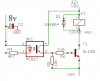
I guys I have an auto-coupler PC187 ..
And i have CMOS circuit which works on 8v ....
And with the help of this auto-coupler I want to switch my relay...
My relay is 12v and it consumes 100ma to work properly....
It is called an Optocoupler, a PC187 ? are you sure it's not a PC817 ?
Is there a reason you want to use an optocoupler to switch a relay ?
It is not usually done this way.
I am connecting pin1 of optocoupler to positive line... line of 8v...
And pin2 to negative line(in between the resistor R4 is available)
Pin3 to transistor via resistor for switching 12v relay..
pin4 to positive line of 12v supply..
But while changing the resistor R4 value (2.2k and 1k) the problem remains same..
It doesnt switches the relay...
I NOW ALSO GET 6v ON RELAY TERMINALS...
BY REMOVING THE 8V SUPPLY ....
NOW ALSO THE 6V IS APPEARING ON RELAY TERMINALS..
IN SHORT.... WHILE REMOVING OR GIVING 8V SUPPLY TO THIS OPTOCOUPLER, IN BOTH CONDITION I AM GETTING 6V ON RELAY ....
SO THIS 12V RELAY DOESN'T WORK...
he gets noise resetting the circuit as he tries to switch the mains operated nearly 1HP motor on this relay contact. now the medium power transistor is under driven, thus suggesting to increase the base current.
This site uses cookies to help personalise content, tailor your experience and to keep you logged in if you register.
By continuing to use this site, you are consenting to our use of cookies.