Continue to Site

Welcome to our site!

Electro Tech is an online community (with over 170,000 members) who enjoy talking about and building electronic circuits, projects and gadgets. To participate you need to register. Registration is free. Click here to register now.

  • Welcome to our site! Electro Tech is an online community (with over 170,000 members) who enjoy talking about and building electronic circuits, projects and gadgets. To participate you need to register. Registration is free. Click here to register now.

How to drive a high voltage generator module

Status
Not open for further replies.

Futterama

Member
Hi forum,

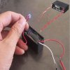
I have a few of these high voltage generator modules from ebay, search for "DC 3V to 7KV 7000V Boost Step-up Power Module High-voltage Generator" on ebay if you want to see more than the attached picture. I'm going to use it for creating a strong spark for igniting propane, like in a spud gun.

I'm trying to control it using a PIC microcontroller, but the module seems to generate so much electrical noise that it will reset the PIC even when the two are not electrically connected, but the PIC is just sitting on the same breadboard where I also put a MOSFET and battery connector to drive the HV module.

I'm driving the module from a dedicated LiPo cell so that the power for the module is separate from the rest of my system. I used a TO-220 N-channel MOSFET for switching the module on/off and I even added an optocoupler so the PIC could be electrically separate from the module.

How can I make the PIC turn the module on/off in a reliable way? I'm going to have other electronics (RC servos and a receiver) near this module so I cannot have it interfere with everything around it.

Are there any general rules about HV I need to consider? Like keeping the HV wires short? Maybe even shield them? Keeping the supply wires from the battery to HV module short and then have longer wires from PIC to optocoupler?

I have also considered using one of those modules used to generate the spark plug voltage in gasoline powered RC planes, but those modules are far more expensive, bigger and heavier, but I guess they don't interfere too much with other electronics since they work in RC planes. I would like to archive the same with these cheaper modules if possible.

Thanks.

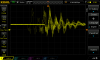
EDIT: I have also attached a scope shot of the battery supply wires with the HV module powered.
 

Attachments

  • highvolt.jpg
    highvolt.jpg
    33.2 KB · Views: 233
  • DS1Z_QuickPrint4.png
    DS1Z_QuickPrint4.png
    50 KB · Views: 195
Last edited:
The module contains a high-frequency oscillator, so any attached wire is likely to behave as an antenna radiating interference. Keeping all wiring as short as possible will help, but you may need to provide electrical screening around the module.
 
The module contains a high-frequency oscillator, so any attached wire is likely to behave as an antenna radiating interference. Keeping all wiring as short as possible will help, but you may need to provide electrical screening around the module.
Hi alec_t, thanks for your reply.

I don't have much experience with shielding electronics, are we talking EMC shielding? Like the very good illustrative page I found below?
https://learnemc.com/practical-em-shielding
 
Like the very good illustrative page I found below?
Just so. You could also try adding capacitance across the module supply pins to decouple the supply.
 
Put the pic in a metal box and switch a relay to power the generator, feedthrough capacitors can be used to reduce emi.
 
Get rid of the breadboard because its many rows of contacts and wires are antennas that pickup interference from the high voltage spark. Make the PIC circuit compact and on a pcb mounted in a grounded metal box.
 
Thanks for all the suggestions. It made a huge difference just to shorten the HV wires, and I'm also thinking I should minimize the loop area of the HV wires, is that correct?

It won't really matter much to encase the PIC in a metal box since it's the module that's the problem, as mentioned, I have other electronics nearby that I cannot risk being interfered, so if the PIC is affected, there is a good chance the other electronics are affected too.

Let's assume I want to shield the HV wires, as they seem to be the major contributer to radiated noise. To which circuit should I connect the shield? The HV modules seems to be isolating the HV side from the supply side. Would it be a possibility to let one of the HV wires be a shield to the other? I'm thinking this would cancel out the noise due to a low loop area, but I'm just brainstorming now, I don't know much about this topic.
 
I searched at bit around for some more info on those HV modules and found this video from Sparkfun where they run long HV wires right next to an Arduino, so maybe it's just the breadboard that is causing my troubles? I haven't made a PCB for it yet, I still don't know if I will go with the optocoupler or not, I'll maybe have to add 2 of them, one between HV module driving MOSFET and PIC and one between the PIC and whatever I have that tells the PIC to start making sparks.

Oh, and here is the video, see how close they route the HV wires to the Arduino and they don't mention optocouplers between Arduino and MOSFET bank.
Jump to 7:22 to see the "spark gap ignitor" circuit I'm referring to.

 
I think the breakdown voltage rating of a shielded cable is fairly low because they never are used with high voltages.
 
Cars have AM radios that pickup sparks which creates "pop" sounds.. Many cars in North America use spark plugs and high voltage wires that feed them. The radios pop for every spark but the cars never used shielded cables because they would breakdown by the high voltage. Instead they use resistive high voltage wires that limit the current feeding the spark plugs.

When I was a teenager I made a fan powered from an old electric motor. The RF cops visited me and confiscated my fan because the sparking brushes in its motor caused radio and TV interference to hundreds of people.
The SparkFun high voltage module uses such a high current and makes such a loud noise that it probably causes radio and TV interference all over the country.
 
I guess I could try to use resistive wire for the HV wires. Would it give the same just to add a resistor in the HV circuit? How much resistance are we talking about, a few ohms or something in the kΩ range? I don't think I can get more than 20Ω per meter with resistive wire, otherwise it gets too thin, so if I need to keep the wires short at the same time, I don't get much resistance with resistive wire.
If I can use a resistor, do I need a special HV resistor o

The question regarding loop area of the HV wires is still open for suggestions :)
 
I never measured the resistance of spark plug wires for cars and I do not know the length of the shortest one.
 
If I were to put the spark inside a steel container, like a 3" long 2" ID steel tube with 1" openings in each end, would it be possible for any of the noise to escape that container through those end openings if they are smaller than a wavelength?
 
Why don't your plants like to hear noise? You don't like to hear noise? The noise from a sparking high voltage is wideband so it has many wavelengths and of course it will be heard outside your metal tube.
 
Status
Not open for further replies.

Latest threads

New Articles From Microcontroller Tips

Back
Top