Continue to Site

Welcome to our site!

Electro Tech is an online community (with over 170,000 members) who enjoy talking about and building electronic circuits, projects and gadgets. To participate you need to register. Registration is free. Click here to register now.

  • Welcome to our site! Electro Tech is an online community (with over 170,000 members) who enjoy talking about and building electronic circuits, projects and gadgets. To participate you need to register. Registration is free. Click here to register now.

how to drive a 0.4 ohms load?

Status
Not open for further replies.
Yes, of course, which is what lots of folks seem to have been suggesting here, with the suggestion falling on deaf ears ...

Mine is more of a pedagogical point (IOW, I'd like to learn something from this): what happens to the impedances of amplifiers in parallel?

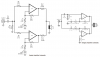
If you check the 'chipamp' datasheets they give connections for two chips in parallel, using low value resistors to balance them.

As you said, you can (under certain conditions) parallel amps; but I think the O.P. is under the mistaken impression (at least I think it's mistaken) that amplifier impedances behave much the same as, say, resistances in parallel. The thinking seems to be "If I have 10 speakers in parallel (a load of 0.4Ω). then hey, I'll just put 10 amplifiers in parallel, with a total impedance of 0.4Ω, so they should match."

Has he ever even mentioned the ratings of the speakers?, will each speaker handle 68W (or whatever it is).
 
But Nigel, can you tell me in general what happens to the impedances of amplifiers when connected in parallel? (Looking at the amps as "black boxes", I guess.) If you don't mind going off on yet another tangent here ...
 
But Nigel, can you tell me in general what happens to the impedances of amplifiers when connected in parallel? (Looking at the amps as "black boxes", I guess.) If you don't mind going off on yet another tangent here ...

Please do not blame me!!! deaf?!! I actually know What I meant by Phase difference of the separate amplifiers which may affect the directivity pattern of a line speaker array. (I just did not know how much of phase difference I would get by using separate amplifiers/speakers)....

regarding your question about paralleling the amplifiers, what will happen is that the final output voltage remains constant while the current delivering of ability of the set will be ten times more. It is similar of paralleling several of the same batteries so that getting more current out of them.....
 
Please do not blame me!!! deaf?!! I actually know What I meant by Phase difference of the separate amplifiers which may affect the directivity pattern of a line speaker array. (I just did not know how much of phase difference I would get by using separate amplifiers/speakers)....

You won't get any, it's NOT a problem - how do you think the massive PA systems used at big gigs work?.

regarding your question about paralleling the amplifiers, what will happen is that the final output voltage remains constant while the current delivering of ability of the set will be ten times more. It is similar of paralleling several of the same batteries so that getting more current out of them.....

No, you seem to have no understanding about amplifiers (or speakers) - they will generally destroy each other. If you've got ten amps, and ten speakers, then feed one speaker from each amp - a perfect solution with no drawbacks.
 
And yes I think this saying is correct:
that amplifier impedances behave much the same as, say, resistances in parallel. The thinking seems to be "If I have 10 speakers in parallel (a load of 0.4Ω). then hey, I'll just put 10 amplifiers in parallel, with a total impedance of 0.4Ω, so they should match."

I think by putting the amplifiers in parallel then the net resistance (internal resistance I mean) of the amplifiers will decrease.....
 
You won't get any, it's NOT a problem - how do you think the massive PA systems used at big gigs work?.

Ok thanks for saying that, So I'll try to it and let you know the result. But I hope there were another method using transistors.Actually I have seen kinds of amplifiers used for big horn apeakers which use more than 8 of 2N3055 transistors to drive the speakers...

No, you seem to have no understanding about amplifiers (or speakers) - they will generally destroy each other. If you've got ten amps, and ten speakers, then feed one speaker from each amp - a perfect solution with no drawbacks.[/QUOTE]

Are you mean that if I have a 0.4 ohms load and connect it to 10 amplifiers all in parallel (and all having 0.1 % output resistors), then all amplifiers will be destroyed? Is that because each amplifier sees 0.4 ohms load instead of 4 ohms?
 
Ok thanks for saying that, So I'll try to it and let you know the result. But I hope there were another method using transistors.Actually I have seen kinds of amplifiers used for big horn apeakers which use more than 8 of 2N3055 transistors to drive the speakers...

Of course you have, it's standard design practice - but it's only ONE single amplifier. The amplifier will also be designed to feed 4 ohms minimum, and not usually anything lower (although a few amps will stretch down to 2 ohms).

Are you mean that if I have a 0.4 ohms load and connect it to 10 amplifiers all in parallel (and all having 0.1 % output resistors), then all amplifiers will be destroyed? Is that because each amplifier sees 0.4 ohms load instead of 4 ohms?

No, because you can't simply parallel amplifiers - and (yet again) there's no purpose in doing so, for ten amps and speakers simply feed each speaker from it's own amp.

If you want only a single amplifier, then use a BIG amplifier, and wire the speakers in series parallel to give a sensible impedance - although with ten speakers you're not going to make 4 or 8.
 
Carbonzit,
Don't you know that the output impedance of a modern amplifier is extremely low? 0.04 ohms or less. The spec for it is called "The Damping Factor" and some amps have a damping factor of 1000 so their output impedance is 0.008 ohms. The extremely low output impedance damps resonances of modern speakers.

The applications note for the LM3886 amp shows how to parallel them for more output current so they can drive more current into a low impedance load. Each amp has a series output resistor so that they share the load even if their gains are slightly different (the recommended gain-setting resistors have a tolerance of only 0.1%).
The applications note also shows how to bridge them (completely different from paralleling them).
The applications note also shows 4 amps paralleled and bridged at the same time.
 

Attachments

  • LM3886 paralleled, bridged.PNG
    LM3886 paralleled, bridged.PNG
    40.3 KB · Views: 139
Quotye "By getting the maximum of output power from the speakers (and thus from the amplifier) each speaker will give the maximum of output sound which is needed for me in far-fields (please remind that my design is a liner speaker..)"

Not so as far as I see. Unless you drive thing very hard both the electrical and acoustic systems are linear ( and more so at low amplitude ) Using less power only changes the amplitude of the far field. Almost any design that tries to get maximum power for audio will end up overdriving on peaks and will clip ( very non linear ). This makes all other concerns about fidelity vanish by comparison.
 
Amplifiers in parallel???

Sorry to belabor the point, but so far, nobody has answered the question I posed above, which is this: What happens to the impedances of amplifiers in parallel?

Remember, I'm asking about the general case here, not specifically about the LM3886 or any other particular amplifier. I want to know what the effect on impedance is of paralleling amplfiers, both from the point of view of the amplifier and from the point of view of the load (speakers in this case).

Do impedances simply combine in the same manner as parallel resistances (in other words, according to the formula

Rt = 1 / ((1/R1) + (1/R2) + ... (1/Rn))

as Dr. Power seems to believe?

I don't think it's that simple.

Remember, I'm speaking in general here, not referring to any specific transistor, IC or vacuum tube amplifier.

Curious minds want to know!
 
Last edited:
Well, what about Audio "Guru"'s illustration with two 3886s in parallel--that's from the application note. Apparently they don't destroy each other.

Remember, I'm not asking "How can I put [n] LM3886s in parallel with each other to drive my massive humungous linear speaker array, in such a was so as not to produce any smoke?". I'm asking what happens generally and theoretically speaking to the impedances of amplifiers placed in parallel, and how to compute it. Does one use a Thévenin equivalent? or a Norton equivalent? does one treat the amplifiers as simple voltage and current sources, like batteries? or is the analysis more complex than that?
 
Last edited:
......Remember, I'm not asking "How can I put [n] LM3886s in parallel with each other to drive my massive humungous linear speaker array, in such a was so as not to produce any smoke?". I'm asking what happens generally and theoretically speaking to the impedances of amplifiers placed in parallel, and how to compute it. Does one use a Thévenin equivalent? or a Norton equivalent? does one treat the amplifiers as simple voltage and current sources, like batteries? or is the analysis more complex than that?
In theory for identical amps in parallel the output impedance will be the output impedance of one divided by the number of amps. But note that to safely parallel the amps you need to add a small resistor in series with each output (0.1 ohm in the example to avoid current hogging). Since this resistance is much larger than the equivalent closed-loop output impedance of the amps, then the parallel output impedance will be basically 0.1 ohm divided by the number of amps.
 
In theory for identical amps in parallel the output impedance will be the output impedance of one divided by the number of amps. But note that to safely parallel the amps you need to add a small resistor in series with each output (0.1 ohm in the example to avoid current hogging).

Current hogging; interesting. How's that work?
 
Current hogging; interesting. How's that work?
It's caused by the small difference in output voltage between the amps due to tolerance of the gain resistors. (Notice that they use 0.1% resistors to minimize this difference.) Because of the low output impedance, the amp with the higher voltage will try to drive a large current into the amp with the lower output voltage (basically the voltage difference divided by the sum of the equivalent output impedances). Thus a small output resistor is added to minimize this.
 
carbonzit,
That's how taking 2 amplifiers in parallel works,

dr.power explained how it works by an example of paralleling the batteries.
Each source (in this cause the amplifier) can be assumed or modeled as a voltage source in series with a resistor (this resistor determines the current and voltage limitation of the output of the source). by paralleling 2 amplifiers you just can convert a Thevenin to Norton conversion and see that you will have a current source with a resistor in parallel across it having a resistance of halved (Req=1/R1 +1/R2) with another norton to Thevenin you'll see that the equivalent series resistor would be halved which means that the source is able to give you twice current than when it was alone....
 
Last edited:
My example of the paralleled LM3886 amps allows more output current so they can drive a 4 ohm speaker at a higher power (about 110W).
 
Well, what about Audio "Guru"'s illustration with two 3886s in parallel--that's from the application note. Apparently they don't destroy each other.

I also mentioned the same application, but without the reference - it works by only using two chips in parallel, by been fairly accurately duplicated chips, and by using low value precision resistors to share the mismatch.

I wouldn't have thought it's something you would calculate?, or would want to? - it's a VERY basic thing you just don't do, and it's rare there's ever any reason to want to (and the 3886 case is pretty much just to show how good the chips are).
 
Ok, Thank you all guys,

I want to try 10 separate LM3886's for the job.
I have got a question regarding the input connection for 10 LM3886's. The schematic which I want to use is in the below pic.

The question is that Can I connect all inputs of the LM3886's directly connected together or there is any trick I should do for doing so?
connecting all inputs then is the total input impedance of the LM3886 circuit becomes 1/10?

Thanks
 

Attachments

  • lm.PNG
    lm.PNG
    26.5 KB · Views: 114
Status
Not open for further replies.

Latest threads

New Articles From Microcontroller Tips

Back
Top