Continue to Site

Welcome to our site!

Electro Tech is an online community (with over 170,000 members) who enjoy talking about and building electronic circuits, projects and gadgets. To participate you need to register. Registration is free. Click here to register now.

  • Welcome to our site! Electro Tech is an online community (with over 170,000 members) who enjoy talking about and building electronic circuits, projects and gadgets. To participate you need to register. Registration is free. Click here to register now.

How to current limit the output of this circuit?

Status
Not open for further replies.

Evalon

New Member
Hi,

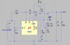
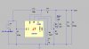
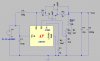
Help would be appreciated with this circuit... I need to be able to current limit the output in a very simple way so that it fulfills these criteria:

- only a few components used
- current limiting need not be very precise (+/- 50 mA),
- it is a solution that has a very low power consumption
- the short-term output voltage remains stable (+/- 15 mV, long term variations of +/- 50 mV acceptable) at an output current of max. 1.5 A.

Please also note that I do not use the LT1082 device but instead the LM2585. Its datasheet can be found here: **broken link removed**

For this reason the Vc pin is called Comp on the LM2585 IC. Other pins are identical as far as I can see.

In practice I have also made it into an adjustable boost converter meaning that the output voltage can be adjusted from ~23 volts to 63 volts DC with a 50k potmeter. It should still be possible to adjust the voltage when the current limiting is in place.

Suggestions are appreciated.

Greetings,

Jesper
 

Attachments

  • step-up.jpg
    step-up.jpg
    128.6 KB · Views: 577
Last edited:
In power grid systems, there is something called "fast reconnection system"* that disconect the load for a short period of time and then tries to reconnect. But this however doesn't meet your first demand about as little components as possible.

Second: A fuse can be used. But your last demand won't be met then.

If you somehow connected a PNP transistor with a low valued resistor between base-emitter, then you shall be able to make this one draw some current. How to achieve it depends on how the regulator is controlled. A little turn off is that you'll have a little voltage drop of maximum 0,7V at maximum load (as you define) that will eat some effect.

So there is several solutions to this problem, but I think there is not possible to make it meet all your demands. I think you need to choose a balance between efficiency and complexity.


*spelling taken from google translate and a little guessing, please correct me if somebody native english know what I mean
 
If you somehow connected a PNP transistor with a low valued resistor between base-emitter, then you shall be able to make this one draw some current. How to achieve it depends on how the regulator is controlled. A little turn off is that you'll have a little voltage drop of maximum 0,7V at maximum load (as you define) that will eat some effect.

Hi Grossel,

- thank you for replying and suggesting solutions. I would be interested in seeing how the circuit in the above quote is designed in practice - I am not sure I understand where the pnp should be placed or connected .... ?

And then I've also considered it further myself and have come up with the solution shown in the attachment.

My idea is that J2 is a constant current generator which in combination with the variable resistor R1 sets a ~constant voltage between gate & source of J1, Vgs. This eventually causes J1 to conduct a current proportional to Vgs when switching voltage is above output voltage (+ probably a couple of volts).

By placing the circuit here, the LM2585's voltage regulation is still in place and by keeping the diode I hope to share a bit of the reverse voltage (I'm not sure this is the correct term) between the diode and the mainly J1. That is, if the output is e.g. 60 volts, and input 20 volts, there will be a reverse (DC) voltage of e.g. 40 volts that should be sustained by the diode and mainly J1 in series.

The hopefully only drawback is that it will sacrifice some of the circuit's efficiency ....

Any of you knows if this may work?

Thanks for considering,

Jesper
 

Attachments

  • step-up2.jpg
    step-up2.jpg
    140 KB · Views: 347
Last edited:
Hello,


The PNP transistor current limit is quite easy to do. You take a PNP transistor, connect the output of the circuit to the emitter, take the new output from the base, connect a low value resistor between base and emitter (say 0.6 ohm for 1 amp current limit) and connect the collector to the feedback Vc. In addition it helps to add a 100 ohm resistor in series with the base (directly in series before the low value resistor) to help prevent a surge in base current from destroying the transistor.
The idea is that when the current becomes high the 0.6 ohm resistor drops about 0.6 volts and this turns the transistor on slightly and that puts more voltage at Vc so it fools the chip into thinking that the voltage is now too high so the chip starts to cut back. The transistor is much faster than the chip internals so it is pretty stable.
The drawback is the 0.6v drop unless you can stand a much higher current limit.
In some cases you need to also add a series diode in series with the base and the new output in order to produce a larger voltage drop. This is sometimes needed to allow the transistor to properly drive the Vc pin even with a very low output resistance. It partly depends on the nominal level of Vc. If it is 1.25 volts you probably dont need this, but if it is 2.5v you may need it. In any case, you need to carefully check the current limit feature after installation to make sure it will truely current limit down to whatever load resistance you think might appear on the output during normal operation. If it doesnt work quite right then you may need to add the diode.
Another possibility is to install the transistor on the input and still drive the Vc pin the same way, but again check to make sure it works as intended.
 
Last edited:
Thanks MrAl, I appreciate your suggestion ;)

I have drawn it up in the schematic - as I read it should be (?) - and have attached it to this post. Can I ask you to just check that wiring etc. is correct?

Also, I have looked in the LM2585 datasheet to see what the reference voltage on the feedback pin is, and it is 1.25 volts. So, since the current limiting need not be too precise I hope this will work ....

Thanks again to both of you - indeed a help with forums and people like you :)

Jesper
 

Attachments

  • step-up3.jpg
    step-up3.jpg
    138 KB · Views: 439
Hi again,


That drawing is almost correct, the only thing that needs to be changed is the output caps need to be connected right to the diode D1 cathode. The way it is connected now it may limit peak current to the capacitor, which isnt really the output current.
Remember to test it too.
 
Last edited:
Thanks MrAl - I'll change the circuitry accordingly. And will test it :)

Greetings Jesper
 
Last edited:
Hi - just to say that I've tried it out now and it works fine :) Thanks for your assistance & the best for your Christmas & New Year.

Jesper
 
Hi again,


Oh great, good to hear. Take care now and happy holidays.
 
Status
Not open for further replies.

Latest threads

New Articles From Microcontroller Tips

Back
Top