Electro Tech is an online community (with over 170,000 members) who enjoy talking about and building electronic circuits, projects and gadgets. To participate you need to register. Registration is free. Click here to register now.
Welcome to our site! Electro Tech is an online community (with over 170,000 members) who enjoy talking about and building electronic circuits, projects and gadgets. To participate you need to register. Registration is free. Click here to register now.
This is the one that they had on eBay and it looked more useful. I figured that a buck/boost converter might help to increase the current from the solar panel to the load whilst regulating the voltage.
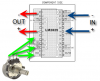
Do I connect the red postive wire to the IC's input wire and the IC's output wire to the pot and then on to the load? I have a wire connected to the IC's GND and I assume that I simply connect this to the pots GND leg.
What do I need to do with the negtive power wire or does this by pass the circuit and connect directly to the load?
This is the one that they had on eBay and it looked more useful. I figured that a buck/boost converter might help to increase the current from the solar panel to the load whilst regulating the voltage.
What you are describing is a "maximum power point tracker" for your solar panel. A simple buck converter won't do that but it will still regulate the voltage. You'd need to add extra control circuitry to your chip to make it behave like a "maximum power point tracker" but it's not really worth it for a small solar panel.
What you are describing is a "maximum power point tracker" for your solar panel. A simple buck converter won't do that but it will still regulate the voltage. You'd need to add extra control circuitry to your chip to make it behave like a "maximum power point tracker" but it's not really worth it for a small solar panel.
I already have a 40amp maximum power point tracker charge controler. I am intending to use the 8w panel to generate power merely to power my projects with variable votages.
Any idea as to how I need to do to wire this IC up to get it to work.
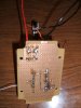
You've been shown several times how to wire it, connect it like the PCB layout. You've also not posted a photo of the bottom of the board so we can't comment on how it's wired.
You've been shown several times how to wire it, connect it like the PCB layout. You've also not posted a photo of the bottom of the board so we can't comment on how it's wired.
I have connect it like the PCB layout. It looks a bit messy however I have tested the IC's holder pin layout and it is correct. It's the IC's power, input, output and GND wires that I'm unsure about.
This site uses cookies to help personalise content, tailor your experience and to keep you logged in if you register.
By continuing to use this site, you are consenting to our use of cookies.

")