Hello Guys
I'm new to electronics and I need some advise on how to correctly connect/wire up a IC.
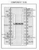
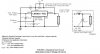
I've just bought a LM2825-ADJ 1A DC-DC buck converter. Which pins do I connect a potentiometer (regulates output voltage) and black and red power wires to?
https://www.electro-tech-online.com/custompdfs/2008/02/LM2825.pdf
I'm new to electronics and I need some advise on how to correctly connect/wire up a IC.
I've just bought a LM2825-ADJ 1A DC-DC buck converter. Which pins do I connect a potentiometer (regulates output voltage) and black and red power wires to?
https://www.electro-tech-online.com/custompdfs/2008/02/LM2825.pdf


")
