Electro Tech is an online community (with over 170,000 members) who enjoy talking about and building electronic circuits, projects and gadgets. To participate you need to register. Registration is free. Click here to register now.
Welcome to our site! Electro Tech is an online community (with over 170,000 members) who enjoy talking about and building electronic circuits, projects and gadgets. To participate you need to register. Registration is free. Click here to register now.
Dear Freands
hi
im interesting for control by printer port
i can control with some of leds about 8 lines witch be out pins in printer port 2-9 , but i wont to control with 250 leds so if any body can help me about create a circute to do it please im waiting
I hope english is not your first language, because if it is, you need to take some remedial language classes
Shift registers or microcontrollers, maybe some cascaded 4:8 decoders (I'm pretty sure you combine two of them, but I'm not sure how) would be the best ways I can think of.
well it depends on how you want to control them. if you just have one led max turned on, then you would need somthing like 8 to 128 decoder, or 8 to 256 decoder.
but if you want to have more than one led turned on, then you could use a flip flop for each led(250?!) so than it wil require a pulse to turn on the led and one pulse to turn it off.
hope someone has more ideas.....
I was going to build the same thing a while ago but never actually built it. I’m not sure if is the easiest way to do it but it uses easily obtainable parts.
As bogdanfirst said if you use a decoder then the decoder can only address one led at a time, which makes for a pretty boring project. So you can use flip-flops to give the leds a sort of basic memory. But it does mean that you need a flip-flop for every led. Once the decoder addresses the specific led then the flip-flop will toggle and what ever state it was (i.e. on or off) it will change to the opposite.
So if you want to turn led number 8 on then you simply pass the number 8 into the decoder through the parallel port of the computer which is connected to the decoder. The decoder will then send a high signal to the corresponding flip-flop. This flip-flop will then change from a low to a high output (assuming it was originally on low). To turn the 8th led back off you pass another number to the decoder to make the input of the flip-flop goes low (the led will still be on) and then address the 8th led again causing the flip-flop to toggle and change back to low (or off). I hope that wasn’t too confusing.
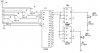
I quickly made the schematic below but it is not complete, I have only put two leds on the decoder. Your version would probably have a larger decoder and a flip-flop led pair on ever output of the decoder. I also don’t know what flip-flop or decoder you should use, these ones were just the first ones I found in the parts list, maybe someone could quote some specific part names that could be used.
Please ask if you need any more help of if you are confused on how the flip-flops or circuit works.
250 LEDs ... Are you sure ? Why not 256, it would be a whole lot easier...
You have no idea how badly I want to tell you to just get up and turn the light switch on, it would be a whole lot simpler
Actually, it should be 255, as you need to reserve one of the states as the all-off state :lol:
Anyway, the idea as others have mentioned, is simply cascade decoders to form 8-256 decoder to turn on any single LED. Cycle through the ON-LEDs to get a virtual effect that multiple LEDs are lit at the same time.
A chip now made by Micrel called MM5451 will drive 35 non-multiplexed led's at a time with a synchronous (two-wire) serial interface. Here's a link to a datasheet: https://www.electro-tech-online.com/custompdfs/2004/08/mm5450.pdf. You could use eight of these, one for each data bit (0-7) on the parallel port. Connect all the clock lines together and drive them from the port's strobe line to clock in the data. Using this method, you could control up to 280 leds at a time. National Semiconductor used to make this chip, but they discontinued it. JB
Try this site: **broken link removed**
Check out the "How To" sections. There at leat 3 designs posted that will do what you want. Simplest uses 74HC575 serial shift register driven from parallel port data pins. You can chain them together for any word length, and even use them from multiple bit pins for virtually any size project you want to control.
Additionally there are 2 other designs based on an multi write addressable data array concept.
Dialtone
This site uses cookies to help personalise content, tailor your experience and to keep you logged in if you register.
By continuing to use this site, you are consenting to our use of cookies.

")