Continue to Site

Welcome to our site!

Electro Tech is an online community (with over 170,000 members) who enjoy talking about and building electronic circuits, projects and gadgets. To participate you need to register. Registration is free. Click here to register now.

  • Welcome to our site! Electro Tech is an online community (with over 170,000 members) who enjoy talking about and building electronic circuits, projects and gadgets. To participate you need to register. Registration is free. Click here to register now.

How to connect this multi-usb module to my voltage regulator

Status
Not open for further replies.

Purp17

New Member
Hey guys, I don't know electronics stuff like this but this is our school project. I don't which part on the usb module to connect my regulator. I hope you will me. I badly need it. IMG_20201130_194210.jpg
 

Attachments

  • IMG_20201130_211957.jpg
    IMG_20201130_211957.jpg
    5.3 MB · Views: 187
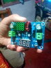
The top connecto on the USB board is the input.
The left of the four pins (as it is in the photo) is the +5V one, the right of the four is the 0V side. The middle two are the computer data connections.

If you are trying to make a multi-way charger, I do not know how well that will work.

It looks like a USB switch module, intended to run from a normal USB socket on a computer. Those are only rated at half an amp (500mA) so that, or not much more, could be all you draw from the other sockets in total.

There is also a possibility that it will not do anything at all, depending on if the switch IC on it includes individual power monitoring and control; it may not provide any power without a computer feeding it.

All you can do is try it and see what happens.
 
Status
Not open for further replies.

Latest threads

New Articles From Microcontroller Tips

Back
Top