Electro Tech is an online community (with over 170,000 members) who enjoy talking about and building electronic circuits, projects and gadgets. To participate you need to register. Registration is free. Click here to register now.
Welcome to our site! Electro Tech is an online community (with over 170,000 members) who enjoy talking about and building electronic circuits, projects and gadgets. To participate you need to register. Registration is free. Click here to register now.
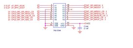
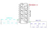
I have the following Buffer IC from TI 74LV244 below. How do I check whether the chip bad or damaged or data is not passing through? Any help direction would be greatly appreciated
1V input swing is not enough to give reliable operation at 3V.
The 74LV244 data states a maximum low input of 0.8V and a minimum high level of 2V (same as 5V TTL logic levels) when operating on or around 3.3V supply, so a minimum signal swing of 1.2V, IF it's perfectly biased to the appropriate range centred exactly on 2.4V
Too low or too high with such a small swing will give erratic operation, if anything.
For reliable operation and noise immunity, the input swing should ideally be from near 0V to something greater than 2.5V
The '244 inputs are schmitt triggers (at least on the bipolar versions; it's not clear on CMOS ones) so have hysteresis by design to prevent false switching.
The output swing will be near equal to the supply voltage, as long as the load is not excessive.
This site uses cookies to help personalise content, tailor your experience and to keep you logged in if you register.
By continuing to use this site, you are consenting to our use of cookies.