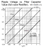
Since the capacitor is usually used at the input of a regulator, the current discharging it is constant. If powered by the AC line, assuming full-wave rectification, the capacitor must supply current to the regulator for 1/2cycle (8.3ms or 10ms, depending if it is 60Hz or 50Hz)
The Charge Q (Coulombs) removed from the capacitor is Q=I*t, where I is current and t is time.
Q also = C*ΔV, where C is the capacitance and ΔV is the voltage drop as the current flows out.
So C*ΔV = Q = I*t
Rearranging gives C = I*t/ΔV.
For a 2A power supply, 60Hz, full-wave, where you can tolerate a 3V sag in the filter capacitor voltage without the regulator dropping out of regulation,
C = 2 * 0.008/3 = 0.0053F = 5300uF
Its not ripple that is important; it is how low does the voltage sag in order not to violate the dropout spec for the regualtor