Hi guys.
Recently I have found an electronic kit at home that I bought on eBay some months ago. I have no idea how to start building it because as far I can remember I have not instructions and also no experience at all.
I have been searching on my email to know where I bought it and I checked the website and they offer no information.
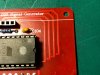
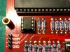
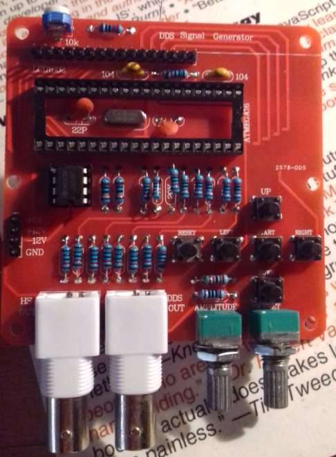
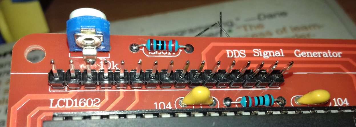
So, at the moment I have all these electronic components:
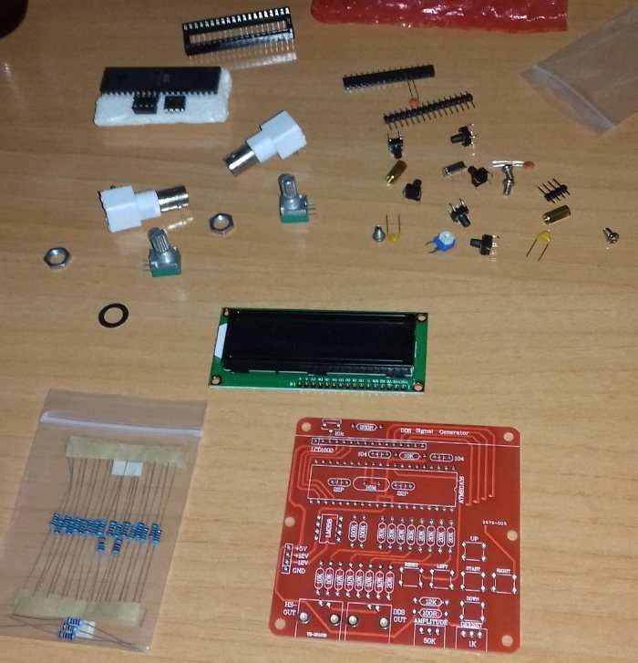
Before starting building it, I want to know if it is possible to feed power with an ordinary battery (maybe with 9 volts one?) or I need an additional circuit to power this circuit.
If the answer is that I can power the circuit without any additional circuit, then I want to start building this circuit but I don't know where to start.
Thanks.
Recently I have found an electronic kit at home that I bought on eBay some months ago. I have no idea how to start building it because as far I can remember I have not instructions and also no experience at all.
I have been searching on my email to know where I bought it and I checked the website and they offer no information.
So, at the moment I have all these electronic components:
Before starting building it, I want to know if it is possible to feed power with an ordinary battery (maybe with 9 volts one?) or I need an additional circuit to power this circuit.
If the answer is that I can power the circuit without any additional circuit, then I want to start building this circuit but I don't know where to start.
Thanks.