Continue to Site

Welcome to our site!

Electro Tech is an online community (with over 170,000 members) who enjoy talking about and building electronic circuits, projects and gadgets. To participate you need to register. Registration is free. Click here to register now.

  • Welcome to our site! Electro Tech is an online community (with over 170,000 members) who enjoy talking about and building electronic circuits, projects and gadgets. To participate you need to register. Registration is free. Click here to register now.

how to build a circuit that acts like this

Status
Not open for further replies.
how to build a circuit that acts like this graph
https://i32.tinypic.com/ivfipx.gif

i am only allowed to use a linear components
a simple diode,simple E1 source simple E2 source
simple resistor


i know that the middle climb is a charging capacitor

there so many switching of modes
i dont know how to start thing of that?

i dont want the solution right away

i want guidance so by answering your questions i will get to the
solution myself
 
Two comments:

1) It could be a diode creating the jump at the beginning
2) What happens when a capacitor is full? It levels off.

I might be way off, but hey, you never know :)
 
a diode is like a switch
if it has a negative voltage on it we would have open circuit
then if we switch the voltage to positive
then it will remain an open circuit
but after the transition period it will be short circuit

so i think that it cannot create a jump
 
Hi,

There is a discontinuity in the circuit where it jumps up suddenly.
That means there has to be at least one switch in the circuit.
 
the answer may be

i attach it
 

Attachments

  • Circuit.jpg
    Circuit.jpg
    20.3 KB · Views: 245
  • Output.jpg
    Output.jpg
    23.5 KB · Views: 235
Last edited:
Hello,


Sorry, i couldnt get that three diode circuit to produce the required waveform.
I might have missed something so let me know if so.

Here is a circuit that provides the required waveform using only diodes, resistors,
constant voltage sources, and one input voltage (V1).
Im not sure if this is the kind of solution you wanted or not so take a look...
 

Attachments

  • StrangeDiodeCircuit.gif
    StrangeDiodeCircuit.gif
    22.1 KB · Views: 229
Hi again,


Here is a more straightforward circuit. You can try to figure out why
the resistor values are such that they are and why the voltage levels
are what they are. All the knee places are easy to set with this
circuit.
 

Attachments

  • StrangeDiodeCircuit-02.gif
    StrangeDiodeCircuit-02.gif
    11.2 KB · Views: 221
Last edited:
Hello again,


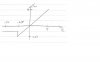
The original waveform has these characteristics in the order shown:

1. The output starts out negative (E2).
2. While the input is still negative, the output jumps up suddenly through zero.
3. The output ramps up, passes through the x axis, then stops rising at E1.
4. The output remains at E1 after that.

The above gives us three corners:
1. At some negative Vin and Vout
2. With Vout positive and Vin still negative
3. With both Vin and Vout positive


I dont see three corners in your teachers solution, only two.

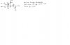
The input starts off very negative, and R conducts and D2 conducts and E2
keeps the output clamped at -E2. As the input rises, eventually it reachs
the same voltage as -E2 and that means there is no current flowing in R
and D2 stops conducting. The output is now still at -E2 though because
the input is at -E2. Now the input rises a bit more and so the output
rises too, but it must be ramping already because Vin is ramping over
time. Thus, the output ramps through zero and does not jump up suddenly
as the waveform picture shows it should.
Eventually the input reachs E1, and then diode D1 clamps the output to E1
so it remains at E1.

What the above means is that there is no jump discontinuity as the original
waveform drawing shows.

You'll have to ask the teacher why the waveform shows a jump when the
circuit given does not seem to have that kind of response.

By adding R2 in the drawing below i can get it to look like a jump
occurs, but the jump only happens near the x axis, not before it.
The entire jump is supposed to be over with before the input
reaches zero. Also, then the output ramps up but there is no clamp
at the end.
I included the original waveform drawing and the circuit your teacher
gave too, and the last schematic is the new circuit but that doesnt
work exactly right either.
 

Attachments

  • 3IVFIPX.gif
    3IVFIPX.gif
    90.6 KB · Views: 226
Last edited:
It's not that circuit.

That circuit clamps the output if input is less then E2-diode drop or greater then E1+diode drop. Between these two points Vout = Vin.
 
Last edited:
Hi,

I gave a full description in my previous post, you may have posted at the
same time that i did.
 
Hi again,


Here is the drawing of the original waveform along with the
teachers solution and the teachers solution with an added
resistor just to show how the resistor forms a slope.
The waveforms for each circuit are shown just to the right of
each circuit.
 

Attachments

  • 4IVFIPX.GIF
    4IVFIPX.GIF
    68.6 KB · Views: 203
Status
Not open for further replies.

Latest threads

New Articles From Microcontroller Tips

Back
Top