Continue to Site

Welcome to our site!

Electro Tech is an online community (with over 170,000 members) who enjoy talking about and building electronic circuits, projects and gadgets. To participate you need to register. Registration is free. Click here to register now.

  • Welcome to our site! Electro Tech is an online community (with over 170,000 members) who enjoy talking about and building electronic circuits, projects and gadgets. To participate you need to register. Registration is free. Click here to register now.

How to build a band pass filter?

Status
Not open for further replies.

gary350

Well-Known Member
I learned this in college 50 years ago but i never used it at work or home projects so I have forgotten how to do this.

I want to build a 3KHz band pass filter. If I remember correctly a coil & capacitor connected in parallel is a band pass filter is that correct? OR is it a coil & capacitor in series?

If I connect a signal generator to a speaker with the band pass filer in 1 of the wires to the speaker it should block all the other frequencies of the signal generator except the 3KHz tone.
 
Yes a band pass filter will block all but the 3khz. If the frequency injected is 30khz then it will be reduced greatly. If the frequency is close like 3.1khz then it will be reduced only slightly. (depends on the Q of the LC used)

Most 2 and 3 way speakers have filters built in. There is a low pass filter so only low frequencies go to big speaker. The tweeter will have a high pass filter before it.
 
How do I make a high Q parallel LC filter?

Does that have to do with the design and value of the coil?

Do certain type capacitors work better than others?

I have a good digital meter I can build my own coils if I know what to build?

I already have a lot of parts, coils, caps, I can test to see what their value is.
 
A series LC makes a fairly poor bandpass since there is only one L and one C. The L blocks some of the high frequencies and the C blocks some of the low frequencies.
A parallel LC in series with a speaker is a notch filter that passes highs and lows but blocks the resonant frequency of the LC.
 
It has been too long since I was in college I have forgotten more than I ever knew. I tried to look this up online and read about it but all I find is how to calculate the Hz of an LC circuit for series & parallel. I'm not finding anything about Q but I remember learning about Q but all I remember is higher Q is better not sure how to get higher Q. Not sure how to build a better band pass filter better than 1 coil & 1 capacitor. I do remember learning about connecting an assortment of different size capacitors in parallel each one filters out a different Hz and some caps make better filters than others. Technology today is surely better than 50 years go there is probably more to learn than I know about.
 
Last edited:
It has been too long since I was in college I have forgotten more than I ever knew. I tried to look this up online and read about it but all I find is how to calculate the Hz of an LC circuit for series & parallel. I'm not finding anything about Q but I remember learning about Q but all I remember is higher Q is better not sure how to get higher Q. Not sure how to build a better band pass filter better than 1 coil & 1 capacitor. I do remember learning about connecting an assortment of different size capacitors in parallel each one filters out a different Hz and some caps make better filters than others. Technology today is surely better than 50 years go there is probably more to learn than I know about.

What EXACTLY are you wanting to do, your questions are pretty vague - if it's to do with speaker crossovers, then it's all done for you.
 
It has nothing to with speakers crossovers. It has to do with sound.

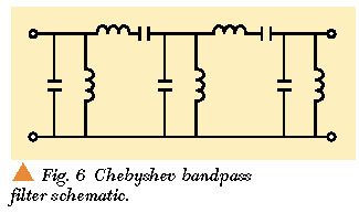
After doing some research & reading I need a series resonance circuit + a parallel resonance circuit like this picture.

22_figure06.jpg


The last 2 in this circuit, LC series then LC parallel on the right side of this circuit picture.

Online LC calculators will not work they all want OHMs or will not do 3000 Hz.

The circuit will need a variable resistor in series with the, series LC circuit for volume.

Series resonance = max current = min impedance at resonant 3KHz

Parallel resonance = max impedance at resonance 3KHz

Online i found test information for 3KHz they use a .3uf cap so I need to calculate the coil to see what coil value i need.
 
Last edited:
I assume you all had an electronic lab class in college. I always liked lab class it was fun and educational too. I am having fun playing in my electronic work shop. It will be fun to build a few projects that I have never built and education too. OH wait, I am retired what will I ever use it for? I don't know & I don't care I am having fun and learning stuff too. Looking at the circuit drawing that I attached the information that I read online says each stage filters out 91% of the unwanted stuff. Math = 91% on the 1st stage, then 91% of the remaining 9% then 91% of the remaining 1%, I think that is how it works.
 
each stage filters out 91% of the unwanted stuff
Filter attenuation is usually referred to in dB (dBv =20*log(Vout/Vin).
Thus a 91% reduction in signal voltage is a 20.9dB attenuation or a rolloff of -20.9dB.
dB is convenient to work with because you just add the attenuation of each stage
Thus two filter stages would have 41.8dB of attenuation and three stages would have 62.7dB
 
It has nothing to with speakers crossovers. It has to do with sound.

You're still not explaining EXACTLY what you're trying to do, but as it's not speaker crossovers it looks like you're going about it completely the wrong way, attempting to make expensive low quality passive filters when cheap high quality active filters would perform many times better for a fraction of the cost.
 
Why do you want to play the sound of only 3kHz? It is a smoke detector's beep sound. A speaker usually plays wideband sounds with a woofer and lowpass filter for lows and a tweeter and highpass filter for highs, without a bandpass filter.
 
Why do you want to play the sound of only 3kHz? It is a smoke detector's beep sound. A speaker usually plays wideband sounds with a woofer and lowpass filter for lows and a tweeter and highpass filter for highs, without a bandpass filter.

I want to hear what the filter is doing. I can put sound through the filter then dial the frequency up & down I should be able to hear sound at 3KHz then sound will be less above and below that. If I built a 2 stage filter then 3 stage filter I should hear the difference. I have no scope to look at filtered sound to put in 2KHz or 4Khz to see how well it works. HOW would you do it if you had no scope?
 
R
HOW would you do it if you had no scope?
I would rectify the voltage with a diode, resistor and capacitor, and measure the average value with a multimeter on its DC range (Edit: See below).
(Most multimeters likely will not work well to measure 3kHz on their AC range).

The ear has a logarithmic response so works poorly to detect the effects of a filter.

upload_2018-7-17_11-55-36.png
 
Last edited:
I've only heard of good things about these, so what about buying one of these? **broken link removed**
 
Your passive filter has low Q since its internal resistance is feeding the low impedance of a speaker so it reduces the levels of frequencies above and below its resonance gradually.
 
Your passive filter has low Q since its internal resistance is feeding the low impedance of a speaker so it reduces the levels of frequencies above and below its resonance gradually.

You keep assuming a speaker (as it's the only sensible option), however while he's declined to give us any information information he has ruled out feeding a speaker.
 
Status
Not open for further replies.

Latest threads

New Articles From Microcontroller Tips

Back
Top