Electro Tech is an online community (with over 170,000 members) who enjoy talking about and building electronic circuits, projects and gadgets. To participate you need to register. Registration is free. Click here to register now.
Welcome to our site! Electro Tech is an online community (with over 170,000 members) who enjoy talking about and building electronic circuits, projects and gadgets. To participate you need to register. Registration is free. Click here to register now.
Hello all
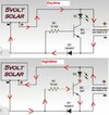
Could you please explain me about the working principle of the following diagram? I could not understand how the transistor works as a switch in this diagram specially how the voltage is divided to turn on the transistor
I suspect it probably doesn't work?, as the panel starts to charge the battery the voltage drop across D1 will increase to around 0.7V, driving the transistor base negative, turning the transistor off even more.
as the panel starts to charge the battery the voltage drop across D1 will increase to around 0.7V, driving the transistor base negative, turning the transistor off even more.
Correct. During charging (daytime), the transistor and LED are off. D1 conducts to complete the charging circuit. At night, the solar panel is a low DC impedance. This elevates the voltage at the left side of R1, turning it on. D1 prevents the panel from discharging the battery.
Correct. During charging (daytime), the transistor and LED are off. D1 conducts to complete the charging circuit. At night, the solar panel is a low DC impedance. This elevates the voltage at the left side of R1, turning it on. D1 prevents the panel from discharging the battery.
Correct. During charging (daytime), the transistor and LED are off. D1 conducts to complete the charging circuit. At night, the solar panel is a low DC impedance. This elevates the voltage at the left side of R1, turning it on. D1 prevents the panel from discharging the battery.
I was under the impression that solar panels usually included an internal series rectifier to prevent discharging the batteries at night, presumably this panel must not have one?.
During the daytime the solar panel is producing 5V. So conventional current flows from the solar panel + to the battery +, this is around the outer loop of the circuit. At night the solar panel isn't outputting anything so current is reversed because the battery is providing the current. Except that current won't flow backwards through D1, so the transistor base turns on.
I was under the impression that solar panels usually included an internal series rectifier to prevent discharging the batteries at night, presumably this panel must not have one?.
Yes, the battery discharges through the solar panel (and in this case the 10K and BE junction) - which is why solar panels usually have either an internal or external rectifier to prevent it.
That is because you are not reading carefully. It comes from the positive terminal of the rechargeable battery, through the low impedance of the non-illuminated solar panel, through the resistor to the base of the transistor.
This site uses cookies to help personalise content, tailor your experience and to keep you logged in if you register.
By continuing to use this site, you are consenting to our use of cookies.