Continue to Site

Welcome to our site!

Electro Tech is an online community (with over 170,000 members) who enjoy talking about and building electronic circuits, projects and gadgets. To participate you need to register. Registration is free. Click here to register now.

  • Welcome to our site! Electro Tech is an online community (with over 170,000 members) who enjoy talking about and building electronic circuits, projects and gadgets. To participate you need to register. Registration is free. Click here to register now.

How do I use this Digital Potentiometer?

Status
Not open for further replies.

Cyclone

New Member
I bought two digital potentiometers from digi-key the other day. I read the data sheet and messed around trying to get the potentiometer to work but I can't. I think I wrecked one of them… I don't understand what their talking about when they explain what the pins do. Can anyone help me out here? I just want to control the brightness of a led using the digital potentiometer to start off with. Anyone willing to explain to me what pins I should connect to what ect?

Help greatly appreciated. :)


https://www.electro-tech-online.com/custompdfs/2003/09/X9C102201032010420503.pdf
 
Are you sure that the device can handle the current/power in this arrangement? I know little about them but it would appear that power handling is limited.
 
the above is right these digital pots are really lame as far as power. 10mw max and at a max voltage of 5V the max current is only 2mA, LED's need more then that. you could use a transister after the digital pot to boost the current
 
ok lets forget about the current aspect of it for now. I would still like to try it out using a volt meter to see the changes in resistence from the digital pot. I still don't understand what the pins do though so i i'm stumped lol.
 
Pin-------explanation
1---------A hi to low transition will increase or decrease resistance
2--------- a Hi is increase resistance when the INC. activated, and low will decrease
3----------High side of POT (connect to the pos voltage, if Voltage is used)
4----------Gnd
5----------Wiper of the pot.
6----------Low side of POT (connect to the GND voltage, if Voltage is used)
7----------The Inc and U/D are enables when this pin is low, disabled when HI
8----------Power

Hope this helps
 
How about just use a simple FET? Btw, I don't know XICOR is also making these devices, I only know Maxim Semiconductor does, so try searching **broken link removed**, they do programmable digital POTS. Btw, these up/down controls I think needs debouncing circuits for you to avoid the bouncing swithch spikes in controlling them.
 
Thanks MicroMan that was a little more helpfull but i'm still stuck.

1. What pins do I connect my volt meter or led to?

2. What pins do I use to increase/decrease resistence and how?

3. What do you mean by "A hi to low transition will increase or decrease resistance "


thanks.
 
It's a digital device not an analog device, so it the pot need to be programmed by sending pulse trains.
 
Yea I know that. I just don't know how. I don't know what their talking about when they talk about high or low transistions. Too bad there wasen't a tutorial on how to use these pots.
 
Transitions is sending a high to low signal or low to high.

IF it s an 2- Wire Device, therefore you must enable the Enable pin first and send the pulse train.

In assembly:

Let us say P2:

setb P2.0 ; set P2.0 to logi 1 (enable, depends on your chip if logic 0 r logic 1)

setb P2.1
pause
clr P2.1
pause
setb 2.1
pause
.... and so on until the bits requiremnt is met.
 
controling LED intensity.

This is a little off topic, but have you considered using PWM instead of an Epot to control led intensity? There's a fair amount of info on both methods under the recent lamp dimmer thread.


Also a very simple 4-resistor D/A idea there which may be the best of the bunch. (just follow it with a single op-amp wired as a voltage follower) - CAL

ps. what the? when did I become a master? and shouldn't there be something like a "journeyman" level between novice and master? :wink:
 
So if a transistion is sending a low or high signal does that mean for example a "high" signal is positive(+9v) and a "low" signal negative(-9v)? or am i totally off lol.


thanks for the link laroche. Most of that stuff was too confusing for me. I'm only a beginner in electroncs ive been doing it off and on for years yea but I only learn bits and pieces at a time. I usually do searches on the net before I post my questions but I usually either find stuff thats way too complicated for me or stuff thats way to basic and non helpfull.
 
Youn need a microcontroller to do it not just a switch. A switch has three states, High Impedance, Shorted to supply or Shorted to ground. A low level means not a negative supply but ground or 0V.
 
what the. ok i'm stupid. I always thought when you see a ground symbol in a schematic that you connect that pin to the negative of your power source. Ive done that in all my projects lol and its worked fine that way.

For example I just finished building this circuit a few days ago. Pin 4 for the op amp i connected to the minus of my power source and all those pins that are connected to ground I also connected to the negative terminal of my power source. lol am I missing something here?

https://www.aaroncake.net/circuits/irrec.gif
 
epots, negative supplies

I didn't mean to overload you, Cyclone. I thought the Epot circuit might help:

https://www.e-insite.net/ednmag/contents/images/32102di.pdf
(scroll down to p. 4)

There is a difference between ground and the -9V supply in your schematic. The op-amp is running off a dual-supply, for ex. two 9V batteries connected in series with the centertap considered ground. Notice that the op-amp is capacitively-coupled to the timer IC, which only runs off the positive supply. Many op-amp circuits use a dual-supply because the outputs can't swing all the way to ground otherwise. Many of the newer op-amps have rail-to-rail output swings and can be run off a single supply.

So, ground is not the same thing as -9V, although the (-) terminal on your battery can be ground. In the diagram below, the (+) terminal on the lower battery is also at ground potential. - CAL
 

Attachments

  • dual-supply.gif
    dual-supply.gif
    3.6 KB · Views: 2,691
thats ok :)


hmmm. Most of the circuits I have used have like +9 volts and the ground symbol. Like this one here.

**broken link removed**


So I always thought ground was the same thing as the negative side of your power source and (-v).


That Infrared schematic uses two 9 volt batteries? Really? And it doesn't use a timer ic. The way I have it connected now I have the op-amp connected to the negative side of my power(-9v) and all those pins connected to the ground symbol in the schematic I also connected to the negative side of my batts. I did a test and instead of connecting those pins to the negative side of the batteries I didn't connect them to anything at all and the circuit still worked. So it didn't seem to make a difference if I connected those pins to the negative side of my batts or didn't connect them to anything at all.


Could you please clarify your post?


thanks for all your help and patience.
 
IR schematic

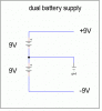
Cyclone, ground usually is the same as the negative side of your power source - when you have a single supply, as in most digital circuits*. Analog op-amp circuits often run off a dual-supply, where the negative supply is not the same thing as ground. Instead, there are (+) and (-) supply potentials relative to ground, as my previous post illustrates.

In the IR circuit,

https://www.aaroncake.net/circuits/irrec.gif

the schematic is drawn showing a dual-supply arrangement, otherwise IC1 pin 4 would be shown connected to ground, not -9V. It's the use of the two different symbols, -9V and GND, that indicate a dual-supply. This circuit probably works fine with a single-supply, since the output from the op-amp doesn't need to swing all the way to ground. What op-amp are you using by the way? Older ones like the 741 don't have rail-to-rail output swings, many newer op-amps do.

(If the circuit doesn't use a timer or one-shot, what is IC2? I assumed it was a timer chip, used as a one-shot)

Like I said in the earlier post, -9V isn't necessarily ground (for example, in a dual-supply), but the (-) terminal on your battery can be ground (the case when you have a single supply). Is that confusing enough?

When you say you left all the ground pins unconnected to anything, the circuit still worked?! That's one failproof circuit! Can't explain that one...

- CAL

*You'll sometimes see positive and negative signals in digital interface circuits as well, true RS-232 levels, for ex.
 
Thanks laroche I understood that much better. So whenever I see -v and ground in the same schematic its I dual supply. Ok i understand that now. :)

Do you think if i use a dual supply for that circuit that I would get better results?

To answer your questions I am using a LM308 Op Amp IC and a LM567 Tone Decoder. I have some 741 op-amps but I haven't found any usefull circuits for them yet.
 
Status
Not open for further replies.

Latest threads

New Articles From Microcontroller Tips

Back
Top