Electro Tech is an online community (with over 170,000 members) who enjoy talking about and building electronic circuits, projects and gadgets. To participate you need to register. Registration is free. Click here to register now.
Welcome to our site! Electro Tech is an online community (with over 170,000 members) who enjoy talking about and building electronic circuits, projects and gadgets. To participate you need to register. Registration is free. Click here to register now.
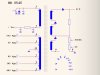
Hi I recently acquired a flyback transformer for the purpose of creating a high voltage power supply but due to my ineptness I was unable to determine which pins were the ones I needed. I do believe I have the basic schematic of the flyback transformer, any assistance is greatly appreciated.
The main high voltage output is normally a wire with thick insulation on it. It will probably have a high voltage diode in it between the transformer and the CRT final anode connector.
I have not seen one with the three secondary windings in series (With the two extra diodes.) All the components shown on the right hand side of your schematic may be encapsulated in a moulding on the transformer and the focus and G2 connections will probably be on this moulding.
Red wire is HV
The orange is for the Focus and G2.
The other pins are probably not like your drawing. (could be)
Do you have a inductance meter?
Do you have a signal generator. (auto 15khz to 30khz) 5 volts signal?
When using the FB transformer you really need to get pin 8 connected to ground.
Hopefully you have a meter. Check the resistance from G2 to pin8 while you turn the pot. Probably the resistance will be in the 2 to 5 mega ohm range.
There should be resistance from pins 1-2 but that pair should not have resistance to any other pin.
Pins 4,5,6,7,9,10 should meter out fine and have no connection to any other pin.
You can not measure any thing on the HV lead.
The high voltage output wire has been cut off. You will not be able to access the high voltage (40kV) easily.
Your primary is usually the two widely-spaced pins all the way at one end of the horseshoe. The two at the bottom in your picture are likely what you're looking for. The other pins are different secondaries, and the only way to really check them is to measure them with a DMM able to withstand the voltage.
I marked the primary.
I put a red circle around a pin that is not in your schematic. It probably has something to do with the HV section/ bleeder/focus pot area.
Do you need all the outputs? If you only need high voltage then most of the other wires can be left open.
Does not have a multiplier.
Does have a high voltage diode on the HV wire.
That pin I circled in red is likely the ground end of the high voltage capacitor on the HV output.
Some times this pin is connected to ground. I connected it to a capacitor/resistor to ground. It is used to filter the HV and to give ripple information back to the HV regulator.
If I had it I would apply 30 volts 32khz across the primary and see what the other leads are doing. That way I would know phase and turn ratio. At 30V not 850V the HV would be low enough that a meter can read.
Could the EHT wire have been cut off or could there be a plug and socket connection on the cylindrical part of the moulding at the top left of your picture. Compare it with the point where the wire comes out of the transformer in the picture that ronsimpson posted. (Post #3) Also what is on the end of the red wire ? If it has the type of connector that connects to the CRTs final anode then it is the high voltage output.
If you connect a led and 47k resistor to a 50 or 60v power supply you have a continuity tester that operates at 60v, you can then use that to find the ground, put one end on the anode cap, then probe around the pins at the base to find the other end of the winding.
The reason for 60v is that the diode rectifier stack in the lopty needs a high voltage to turn on.
This site uses cookies to help personalise content, tailor your experience and to keep you logged in if you register.
By continuing to use this site, you are consenting to our use of cookies.