Continue to Site

Welcome to our site!

Electro Tech is an online community (with over 170,000 members) who enjoy talking about and building electronic circuits, projects and gadgets. To participate you need to register. Registration is free. Click here to register now.

  • Welcome to our site! Electro Tech is an online community (with over 170,000 members) who enjoy talking about and building electronic circuits, projects and gadgets. To participate you need to register. Registration is free. Click here to register now.

How did I do?

Status
Not open for further replies.

metalmckanical

New Member
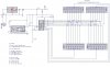
This is one of my first circuits. Could you please check my work for errors?
It is a counting circuit with a 5v regulator. I have attached the schematic.
Is there anything I missed or did not do it right?
I want this to be a robust and reliable circuit.
Thank you in advance.


I have linked the data sheets below
**broken link removed**
LTD-5523AB seven segment common cathode display (blue)
 

Attachments

  • schematic.jpg
    schematic.jpg
    107.3 KB · Views: 215
You need to add a pull-up resistor between Pin 8 of the 7217 IC and +5V for the transistor output of the sensor to work correctly. A value of 1K ohms would normally be used, but this is incompatible with your blue LED D5 which needs current to flow when Pin 8 is high and this current would drop voltage across the pullup resistor. To make the LED work it might be easiest to put the LED and its series resistor from pin 8 up to 5V so that the LED turns ON when pin 8 is low. In this way, the LED and resistor provides the pullup function. It may be necessary to put a large value resistor across the LED, like 22K ohms.

I can infer the connections from the driver IC to the display, but I think this should be shown more explicitly on the schematic.

C4, the 47uF capacitor, is sufficient bypassing along with C3, so I think C1 is not needed. C4 can be an electrolytic type. This assumes these parts are all located on the same board.

You need to decide on the Store function, pin 9. It seems that you may need to ground that input, but check the data sheet.
Pin 10 must be wired to gnd or 5V, it cannot be left floating.
You probably need to put a reset circuit on pin 14 of the IC, or else the counter will power-up to an unknown value. The most common and simple type is to wire a larger value capacitor from the Reset pin to gnd and a resistor from the Reset pin to 5V. The values for resistor and capacitor are chosen so that the capacitor takes much more than 10mSec to charge up to 2.5V. Alternatively, you could use a reset IC.

D3 would be less confusing if you used the symbol for a lamp instead of an LED.

Post again after making corrections.
 
Last edited:
The LED connected to the voltage regulator needs a current limiting resistor or it will be destroyed. I don't know why you have a diode (besides the LED) on the output of your photo-interrupter. The count will never increase the way everything is connected, you need to provide a pull up resistor on the output of the photo-interrupter.
 
Sorry it took so long to get back. Grandmother is in the hospital, so haven't had much time between that and work.

Thanks for the in depth replies. I see I missed quit a bit.
I will post up a revised schematic after making changes.

I might just use a push button switch for the reset pin if I can't figure out/find a reset circuit.
Again thank you for taking the time.
 
The LED connected to the voltage regulator needs a current limiting resistor or it will be destroyed.

Not necessarily, the ICM7217 internaly controls the current through the LED display, although it may increase the power dissipation of the IC. They reccomend using a diode or a 47 ohm resistor in series with with the display to limit power dissipation.
 
I wasn't referring to the displays, I was referring to D3, an LED connected directly between Vdd and Gnd.
 
I finally got it done. Hopefully it's all correct.

-Changes-
>all connections for display are shown
>power indicator 5v led was changed to 2.5v @20ma
>count led is removed
>pull up resisters added to pin 14 and 8
>pins 10, 12, 20 are driven to 2.5v (less floating pins the better)
>momentary switch is added to pin 14
>pin 9 grounded

The 7805 I will be using is KA7805ETU from fairchild. or should I use LM340T and up the power supply to 1.5A so I know I have adequate current?

*ignore R-5. forgot to remove it from parts list.

Thanks again for all the help.
 

Attachments

  • schematic2.jpg
    schematic2.jpg
    275.6 KB · Views: 181
Last edited:
Status
Not open for further replies.

Latest threads

Back
Top