Continue to Site

Welcome to our site!

Electro Tech is an online community (with over 170,000 members) who enjoy talking about and building electronic circuits, projects and gadgets. To participate you need to register. Registration is free. Click here to register now.

  • Welcome to our site! Electro Tech is an online community (with over 170,000 members) who enjoy talking about and building electronic circuits, projects and gadgets. To participate you need to register. Registration is free. Click here to register now.

How cheap 5V car chargers/sources works?

Status
Not open for further replies.
Hi!
Does anybody know how these cheap car chargers work?
**broken link removed**
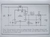
They are small so there is no room for a heatsink, so I guess that they do not operate on the principle of common LM317 or 7805 IC's. They maybe work using the step-down converter? I want to build DIY charger/power source for my GPS (5V/1-2A) for use in car (≥12V) with minimum "easy to find" parts with as little power/HEAT dissipation as possible!

TIA!
 
The ones I have bothered to hack open co0ntain a 7805 with a simple metal tab heat sink. That and a few capacitors.

Ron
 
I'm really surprised! I tried to do this with 7805 and LM117 but the temperature at 117 (which is better, i.e.much less heat) has gone to over 150°C!! Reloadron, Does your device work (or is already housing dissolve by the heat)? Or I do something wrong ...
 
Somewhere around here I should have one that I think failed. If I can find it I'll rip it apart. The last one I tore apart was a few years ago. While the one I tore apart was not identical to what you posted the guts were a 7805 (or equivalent) with no markings, a few caps and a LED. There wasn't much to the thing. Maybe with luck someone else will wander in with more thoughts.

Ron
 
I wouldn't ASS-U-ME that they use a simple linear regulator; I once salvaged some parts from one of those things that had been run over in the street. Inside was a micro buck converter, with a driver chip, MOSFET, inductor and everything.
 
Thanks, Ron, for quick reply. I would really like to know what's inside! Please note: Input 24/12V; Output 5V/1A. There are also the version with 2 Amps in same case! I really do not know how this is possible with the 7805 without the casing does not melt and burn!? (Sorry, my english...:eek:)
Carbonzit, some scheme maybe?
 
Thanks, Ron, for quick reply. I would really like to know what's inside!

Well, there's a really easy way to find out: use a little creative destruction and take one apart.

If you do, please report your findings back here.

And by the way, no, your English is not horrible. I've heard horrible (sometimes from native speakers!), and yours isn't that bad.
 
Last edited:
That's the problem. I'd buy one but I do not know what's inside! I heard about the so-called "buck" converters, I'll search a bit on the net. If someone has a ready scheme let me know please! I need it for charging/power GPS in car - 12(or more)V to 5V, 1.5-2 Amps.

(Carbonzit, thanks for the compliment!!!)
 
Last edited:
You should get ahold of Simon Bramble, who posts here. You can read his page on buck converter design to learn how they work.

If you look at that page, don't be put off by the apparent complexity of the circuits. The basic topology of the classic buck converter is this:

**broken link removed**

The switch, of course, is not a physical switch but a switching device, like a MOSFET or BJT transistor, that can be turned on and off many thousands of time per second by a square-wave driver (not shown here). The coil is what does the power transformation, for the most part. Interesting little devices.
 
Last edited:
The ones Ive pulled apart use this circuit. Which ive modified to change the output voltage. Phone car chargers are the same. The chip does the switching & regulating.
 

Attachments

  • ADJ Phone charger.JPG
    ADJ Phone charger.JPG
    1.8 MB · Views: 1,317
Thank you guys! I think that's the way i'm gonna go (is this well written??:confused:)! Very interesting IC! Now i will study datasheet!
I suppose that with this IC (scheme) I don't have to worry about power spikes and the like that occur in the car while working.
 
The first is based on LM2575. Finished module is not available where I live and is too expensive to me too. The second is a great thing (I WANT IT :)!) but price: even if the basic price stays on 1$ the postage is a little too high (8$)! Thanks anyway!

@debe: Your circuit is very interesting to me. I can get MC34063(AP) relativly easy
(50 km trip) for approx. 1USD. or even better - from ebay -5 pcs for 2,90$! If I understand your scheme well this circuit provides 0.5 A output. Datasheets for that IC says it can give up to 1,5A!? So, would You be so kind, if You know, to "update" the scheme so that output can give at least 1.5 A (2A even better!) with "few" easy to find parts ? TIA!
Btw. is there need for any heatsinks using that circuit?
 
Thank you guys! I think that's the way i'm gonna go (is this well written??:confused:)!

Yes, you're using what's called idiomatic English (that's a good thing).

Very interesting IC! Now i will study datasheet!
I suppose that with this IC (scheme) I don't have to worry about power spikes and the like that occur in the car while working.

Yes; the power supply chip includes regulation, and the input and output filter capacitors should remove any nasty stuff from the output.

What do you mean by "scheme"? Schematic? (the term for an electronic circuit diagram)
 
"Idiomatic English"...hmm... I must google this! :)Just kidding, thanks again :D!
Yes I mean "schematic"! I found on many English-speaking forums and web-pages that (I suppose) native English speakers say "scheme" so I was thinking that's right word. Now I know the difference - THANK YOU!
 
Yes I mean "schematic"! I found on many English-speaking forums and web-pages that (I suppose) native English speakers say "scheme" so I was thinking that's right word. Now I know the difference - THANK YOU!

We say "schematic", not "scheme". A scheme is a plan, often an underhanded one: "He was scheming how to get his hands on his uncle's money".
 
Carbonzit: please feel free to correct my "google-translate" English whenever you want! English was my second foreign language from primary school to university (the first was German - I do not know much more German than "Guten Tag"). English is a much nicer language than German in every way (IMO), but I had no choice to choose English as my first language ...:(
 
Hi guys, look what I found on ebay:
**broken link removed** for only 5 USD!
It can be easily converted into regulated converter.
But what confuses me is this:
**broken link removed** for 18,50 USD ???
Why is chip alone almost 4x expensive than completed circuit ready to use (that includes that same chip)??? Should I avoid the first one???
I need your opinion; finally, can I use this circuit in the car (perhaps with some additional filters, etc.)?

I apologize in advance if i don't reply to your posts immediately. I was awake all night (it is 7am here) and I have to catch some sleep!
 
Last edited:
Status
Not open for further replies.

Latest threads

New Articles From Microcontroller Tips

Back
Top