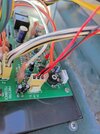
I have a pool heater that I have to replace the electronic control board often. I have now replaced the board 5 times. Each board shows the same issue when it needs replaced. I have tested all of the control switches all test good. The thermister is one item that is not basically an open or closed switch. As I'm sure everyone here knows the resistance value of the thermister changes with temperature change.
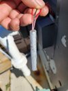
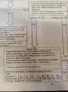
The one I need help with has three wires, ST-COM-SR. The manual shows to test Resistance based on the water temp. So Lets say that the water is at 60*F. The resistance between ST -COM is 15.31(K), resistance between SR-COM is also 15.31(K) within 10% of each other is good.
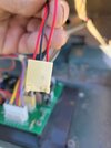
My thermister tests good with my VOM. But I still think that it may be bad. It is a fairly expensive part to just guess needs replacement. So I would like to make a "test" tool with two resisters. Seems simple enough to do use one side of the resisters together for COM then the other side for ST and SR.
But I am not savey enough with electronics to know if this will work or not to"trick the board into "thinking" that it is a working thermister. I also don't know how to choose a resister to give me the correct value of 15.31.
I will replace either the board or thermister after my test. But at this point it is hard to belive that the boards keep going bad with the same symptoms.
Any advice? TIA
Ron
The one I need help with has three wires, ST-COM-SR. The manual shows to test Resistance based on the water temp. So Lets say that the water is at 60*F. The resistance between ST -COM is 15.31(K), resistance between SR-COM is also 15.31(K) within 10% of each other is good.
My thermister tests good with my VOM. But I still think that it may be bad. It is a fairly expensive part to just guess needs replacement. So I would like to make a "test" tool with two resisters. Seems simple enough to do use one side of the resisters together for COM then the other side for ST and SR.
But I am not savey enough with electronics to know if this will work or not to"trick the board into "thinking" that it is a working thermister. I also don't know how to choose a resister to give me the correct value of 15.31.
I will replace either the board or thermister after my test. But at this point it is hard to belive that the boards keep going bad with the same symptoms.
Any advice? TIA
Ron
")