Continue to Site

Welcome to our site!

Electro Tech is an online community (with over 170,000 members) who enjoy talking about and building electronic circuits, projects and gadgets. To participate you need to register. Registration is free. Click here to register now.

  • Welcome to our site! Electro Tech is an online community (with over 170,000 members) who enjoy talking about and building electronic circuits, projects and gadgets. To participate you need to register. Registration is free. Click here to register now.

How Can I Upgrade My Stock Scion 4 Wire Mic + Preamp circuit?

Status
Not open for further replies.

travisbklein

New Member
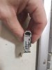
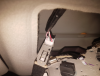
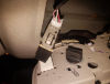
Hello, I have a stock 4 wire mic and preamp board that my 2013 scion uses. The sound is pretty crappy and I want to upgrade to an aftermarket one but I am having trouble.

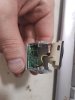
I'm trying to figure out which wires are what on the mic, there are 4 going into the mini circuit board and 2 from the circuit board to the actual mic.

I have continuity from one pin of circuit board to one pin of the mic, maybe this is the ground?

Do you think I could use a normal mic if I found the correct 2 wires and just left the preamp out? Or maybe I need some type of preamp device like this:

thanks so much for any help!
 

Attachments

  • NV5zTa9.jpg
    NV5zTa9.jpg
    612.6 KB · Views: 169
  • CWKTVsz.jpg
    CWKTVsz.jpg
    673.7 KB · Views: 176
  • Photos 2019-12-14 12.16.31.png
    Photos 2019-12-14 12.16.31.png
    742.4 KB · Views: 162
  • Photos 2019-12-14 12.16.21.png
    Photos 2019-12-14 12.16.21.png
    697.8 KB · Views: 176
It appears to use a balanced (differential) output from the mic amp PCB. I've found a drawing that shows the mic module pinout:

I'd try different mic capsules in place of the one in that module, rather than trying to replace the whole thing.

Any basic two-wire electret mic capsule should work in place of the original. Note that the output levels of mic capsules vary phenomenally and a lot of the cheap ebay ones are very poor.
The types you can get at electronics distributors should be better quality and have sensitivity data.


For info, you cannot use a preamp such as the one you link to, as they need 48V fed down the output wires relative to ground (aka "phantom power") to work.

It should be fairly simple to build a suitable preamp to add on to a generic mic capsule.
 
Please explain the details of the "crappy sound" that is produced by the original mic. Distortion, hiss, rumble and hum, muffled high frequency response or pick up of background sounds? If the original mic picks up background sounds that you do not want then is there a way to get the mic closer to your mouth then turn down the mic gain? The 4th wire to the preamp might be to adjust the gain.

You are just guessing about what kind of mic and preamp you have and since Amazon knows nothing about electronics, they do not know what kind of mic their expensive preamp needs.

What kind of mic is a "normal" one? Dynamic, electret or carbon?
 
It appears to use a balanced (differential) output from the mic amp PCB. I've found a drawing that shows the mic module pinout:
Thank you so much for the wiring rjenkinsgb , you are the best! I think that is not a bad idea, nothing really to lose. I'm going to buy one and solder it on and do some testing (after I do more testing on the stock one so I can have a good baseline).


When I am parked and pushing my face really close to the exposed mic, people say it sounds better when I just put my phone on speakerphone and not use that. I guess I need to actually hear it to evaluate it.

I'm not sure I could even guess at what type of mic or preamp is in the car.

A normal car mic would be the ones with 2 wires that are sold online to plug into radios with bluetooth that do not need this preamp circuit that I have.
 
A normal car mic would be the ones with 2 wires that are sold online to plug into radios with bluetooth that do not need this preamp circuit that I have.

Most simple "two wire" mics are actually electret capsules, which use a ground and an output that is also fed power via a resistor.
(There are other types, but they are the commonest).
eg. https://encrypted-tbn0.gstatic.com/...j7K0b6ZfYWmr9N5N6LIbEjdLhHiHLbqozySwwpRbG61&s

The extra circuitry in the module is likely to boost the signal level & drive capability, plus having the two-wire output avoids electrical noise pickup in the wiring.


My car has the built-in mic capsule on a long cable all the way to the voice/bluetooth module behind the radio head unit; it has the same problem as yours, it's not as good as the phone itself on hands free mode.

I've tried other mic capsules but so far they are all worse than the OEM one.
 
do you think I could get this mic working externally and test it with my phone? Power the board with 5v and ground, hookup mic to the other 2 wires?
 
I'd not try that, the voltages or signal levels on the amplified connections may damage something intended for direct connection to an electret capsule.

The two wire mic capsule on its own should work if directly connected to the appropriate contacts on a four-way (trrs) 3.5mm plug.

See the connections here:
 
You did not explain the details of the "crappy sound".
You also do not know if the mic is dynamic (coils and magnet) or electret (condenser type with 48VDC stored in its electret material and it has a Jfet impedance converter that needs to be powered with a 0.5mA DC current).

A dynamic mic might not work if it is fed the current needed by an electret mic.
An electret mic does not work without the DC current it needs.

Since you tried other mic capsules and they all sound worse than the original crappy mic then they are probably very cheap ones. A good electret mic costs a few dollars, a cheap one costs a few cents.
 
I'd not try that, the voltages or signal levels on the amplified connections may damage something intended for direct connection to an electret capsule.

The two wire mic capsule on its own should work if directly connected to the appropriate contacts on a four-way (trrs) 3.5mm plug.

See the connections here:


I found this thread here where they wired a normal dynamic mic , ones that plug into your phone.


I'm moving forward assuming this is a normal everyday mic that can work in audio devices I have in my house.

I'm going to measure what type of voltage and current is feeding this circuit. Then I'm going to see if I can test it on a crappy sound card I will connect to my pc.
 
pic #2 in post #1 looks as if the 4-pin header isn't soldered to the board.
 
I found this thread here where they wired a normal dynamic mic , ones that plug into your phone.

Phones use electret mics, not dynamic! Two very different things.

As I have already said, a normal electret mic should work if you wire it where the existing capsule connects, the two-wire point.
 
Phones use electret mics, not dynamic! Two very different things.

As I have already said, a normal electret mic should work if you wire it where the existing capsule connects, the two-wire point.

the headsets with mics built into them, that plug into phones, mp3 players, ipods, are dynamic mics.

And, got ya, I guess that guy in the other thread used an electret mic, I will give that a try first and see what happens, ty ty ty !
 
the headsets with mics built into them, that plug into phones, mp3 players, ipods, are dynamic mics
Sorry, but you have been given wrong information. Note that many advertisers have no idea what they are selling and very frequently use incorrect descriptions.

Dynamic mic capsules are relatively large; they are a "moving coil" device like a tiny loudspeaker.
The smallest I've ever seen is actually about half an inch diameter and they are used in some professional grade communications headsets.

Electrets are available down to at least 4mm by 1.5 thick and likely smaller.

Dynamic mics are not polarity sensitive and do not need a bias voltage. Any mic capsule with a voltage on it means it's not dynamic...

Note that dynamic mics also have very low DC resistance; the specs for a typical phone mic input require a relatively high resistance so the remote controls, when used, put a readable finite resistance across the mic input - eg:

e6dc96cec070babd539c11eebfff21e9.jpg
 
pic #2 in post #1 looks as if the 4-pin header isn't soldered to the board.
Press-fit. Allows the use of lower-cost non-high-temperature plastic for an SMT assembly, or having to glue down all of the SMT parts for a wave-soldered assembly.

ak
 
Status
Not open for further replies.

Latest threads

New Articles From Microcontroller Tips

Back
Top