No, that circuit cannot be readily converted to be a boost converter.
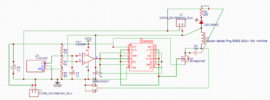
Yes, you just change the divider resistor values to generate 4.2V, or any desired voltage.
The resistor values are selected to give 2.5V at the Ref input when the cathode voltage is 4.2V.
For example, R1=4.75kΩ and R5=6.89kΩ will work.

 ).
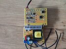
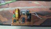
). I wanted to make a coilgun for a long while. I have the thristors and boost converters but one of the boost converters broke at some point and shorted so I need to find a way to fix it first. The only reason I bought the caps was because they were unusually cheap. Got two of them for 6USD total.