Continue to Site

Welcome to our site!

Electro Tech is an online community (with over 170,000 members) who enjoy talking about and building electronic circuits, projects and gadgets. To participate you need to register. Registration is free. Click here to register now.

  • Welcome to our site! Electro Tech is an online community (with over 170,000 members) who enjoy talking about and building electronic circuits, projects and gadgets. To participate you need to register. Registration is free. Click here to register now.

How 3x axis sine waves act on a Compass module Oshonsoft BASIC.

Status
Not open for further replies.
Something like this.
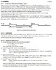
What makes ready bit go high?
See image

dredy:
Testrdy
SPISend 0x82
SPIReceive drdy
If drdy.0 = 0 then ' Test drdy bit
goto Testrdy
Endif

For i = 0 To 5
compss = 0 'CHIP SELECT COMPASS ON
addr = 0x83 + i
SPISend addr
SPIReceive data
b(i) = data
compss = 1 'CHIP SELECT COMPASS OFF
Next i
Return
Hi J,
Result of your CODE:
dredy: 'Test DRDY REG
testrdy:
SPISend 0x82
SPIReceive drdy
If drdy.0 = 0 Then
Goto testrdy
Endif
For i = 0 To 5
compss = 0 'CHIP SELECT COMPASS ON
addr = 0x83 + i
SPISend addr
SPIReceive data
b(i) = data
compss = 1 'CHIP SELECT COMPASS OFF
Next i
Return
......................................................................................
[00][00]Ready!
SELF TEST 255 255 2 1 192 254
AT+C002
-223.00,247.00,-323.00
-224.00,250.00,-318.00
-225.00,249.00,-319.00
-227.00,253.00,-327.00
-230.00,252.00,-318.00
-226.00,244.00,-318.00
-231.00,253.00,-317.00
-233.00,255.00,-327.00
-232.00,244.00,-316.00
-229.00,255.00,-323.00
-222.00,252.00,-324.00
-225.00,247.00,-321.00
-222.00,244.00,-326.00
-231.00,255.00,-321.00
==============================================================
I can see that this is not correct, but does the idea work, if corrected?
dredy: 'Test DRDY REG
For i = 0 To 5
compss = 0 'CHIP SELECT COMPASS ON
addr = 0x82 + i 'STI HXL-HZH'<<<<<<<<<<<<<<<<<<<<<<<<<<<
SPISend addr
SPIReceive data
b(i) = data
compss = 1 'CHIP SELECT COMPASS OFF
If st_1_raw.0 = 0 Then Goto dredy '<<<<<<<<<<<<<<<<<<
Next i
Return
_____________________________________________________________________
 

Attachments

  • DRDY.jpg
    DRDY.jpg
    190.3 KB · Views: 217
What is st_1_raw.0 ?
Where do you test rdy bit or read st_1 ...
Hi J,
Possibly a bit tangled, but generally something like this.
___________________________________________________________
'SELF TEST'+++++++++++++++++++++++++++++++++++++++++++

SPICSOn
compss = 0 'CHIP SELECT COMPASS ON
SPISend 0x0a 'CONFIG CNTL1
SPISend 0x00 'POWER DOWN
SPISend 0x0c 'ASTC
SPISend 0x40 'SELF BIT= 1
SPISend 0x0a 'CONFIG CNTL1
SPISend 0x08 'SELF TEST MODE
SPISend 0x89 'ST1 0x09
Gosub dredy
SPISend 0x0c 'ASTC
SPISend 0x00 'SELF BIT= 0
SPISend 0x0a 'CONFIG CNTL1
SPISend 0x00 'POWER DOWN
compss = 1 'CHIP SELECT COMPASS OFF
SPICSOff

st_1_raw = b(0) 'BIT 0 = DRDY
x_raw.LB = b(1) 'BYTE
x_raw.HB = b(2) 'BYTE
y_raw.LB = b(3)
y_raw.HB = b(4)
z_raw.LB = b(5)
z_raw.HB = b(6)


Hseropen 9600 'After initialisation'??????????????????????????????????
Hserout "Ready!", CrLf

Hserout "SELF TEST ", #x_raw.LB, " ", #x_raw.HB, " ", #y_raw.LB, " ", #y_raw.HB, " ", #z_raw.LB, " ", #z_raw.HB, CrLf

'END SELF TEST'++++++++++++++++++++++++++++++++++++++
======================================================================
dredy: 'Test DRDY REG
For i = 0 To 6
compss = 0 'CHIP SELECT COMPASS ON
addr = 0x82 + i 'STI HXL-HZH
SPISend addr
SPIReceive data
b(i) = data
compss = 1 'CHIP SELECT COMPASS OFF
If st_1_raw.0 = 0 Then Goto dredy '<<<<<<<<<<<<<<<<<<
Next i
Return
_____________________________________________________________
 
I think you should test the rdy bit=1 before reading any of X,Y,Z
Self test from the manual:

(1) Set Power-down mode. (MODE[3:0]=“0000”)
(2) Write “1” to SELF bit of ASTC register (other bits in this register should be kept “0”)
(3) Set Self-test Mode. (MODE[3:0]=“1000”)
(4) Check Data Ready or not by any of the following method.
- Polling DRDY bit of ST1 register
- Monitor DRDY pin
When Data Ready, proceed to the next step.
(5) Read measurement data (HXL to HZH)
(6) Write “0” to SELF bit of ASTC register
(7) Set Power-down mode. (MODE[3:0]=“0000”)

Polling means to read repeatedly St1.0 until it is 1
 
Last edited:
I think you should test the rdy bit=1 before reading any of X,Y,Z
Self test from the manual:

(1) Set Power-down mode. (MODE[3:0]=“0000”)
(2) Write “1” to SELF bit of ASTC register (other bits in this register should be kept “0”)
(3) Set Self-test Mode. (MODE[3:0]=“1000”)
(4) Check Data Ready or not by any of the following method.
- Polling DRDY bit of ST1 register
- Monitor DRDY pin
When Data Ready, proceed to the next step.
(5) Read measurement data (HXL to HZH)
(6) Write “0” to SELF bit of ASTC register
(7) Set Power-down mode. (MODE[3:0]=“0000”)

Polling means to read repeatly St1.0 until it is 1
Hi J,
I must have read that 10s of times, and still baffled by POLLING and READING
C
 
Hi,
The penny has dropped!
READ means the BYTE is in the variable. Poll means is a BIT 0 or 1, got it :)
C
 
Hi J,
This is frustrating.

Here is a READing from the program attached. I'm suspicious about X being 255 255.
Also I get one READing after programming, then if it is switched OFF/ONN then it doesn't READ DATA.
______________________________________________________________________
Ready!
SELF TEST 255 255 222 0 158 254
AT+C002
-155.00,227.00,-351.00
-147.00,227.00,-357.00
-140.00,230.00,-360.00
-142.00,220.00,-352.00
-149.00,223.00,-357.00
-147.00,225.00,-355.00
-146.00,220.00,-360.00
[00][00]Ready!
SELF TEST 255 0 0 0 0 0
AT+C002
-147.00,221.00,-357.00
-148.00,220.00,-350.00
-146.00,232.00,-358.00
-145.00,227.00,-361.00
-139.00,223.00,-351.00
-152.00,228.00,-356.00

NOTE: We've been here before, and I don't think it was settled then. :( Sorry.


C
 

Attachments

  • 18F4520 INT8MHz HC12, AK8963C PCB3 XYZ-SELF_TEST 150920_3.txt
    5.5 KB · Views: 214
X = -1 and is within the limits of the self test ( -200 to +200)
Y= +224, a little bit too high.
Z= -354. Should be -3200 to -800.
Why do you print low byte, high byte?
Print the converted values, it is easy then to check the values.
 
X = -1 and is within the limits of the self test ( -200 to +200)
Y= +224, a little bit too high.
Z= -354. Should be -3200 to -800.
Why do you print low byte, high byte?
Print the converted values, it is easy then to check the values.
Hi J,
I've added 2's compliment to the SELF TEST section.
Here's the results:

Note: When it has been programmed, then switched off/on it shows 255, 0, 0 Does this mean it has re-calibrated any errors?
C.
_____________________________________________________
Switch on from last program
[00][00]Ready!
255, 0, 0
AT+C002
-173.00,211.00,-355.00
-176.00,204.00,-356.00
Program
[00][00]Ready!
255, 199, 157
AT+C002
-184.00,200.00,-352.00
-180.00,202.00,-364.00
-183.00,197.00,-357.00
Switch Off/on
[00][00]Ready!
255, 0, 0
AT+C002
-183.00,201.00,-357.00
-187.00,203.00,-359.00
-172.00,204.00,-362.00
-180.00,208.00,-364.00
-188.00,206.00,-354.00
-176.00,200.00,-358.00
-180.00,198.00,-366.00
Re-program
[00][00]Ready!
255, 201, 153
AT+C002
-189.00,205.00,-361.00
-180.00,200.00,-344.00
-176.00,202.00,-368.00
-176.00,198.00,-356.00
-188.00,204.00,-360.00
-180.00,200.00,-356.00
Switch Off/on
[00][00]Ready!
255, 0, 0
AT+C002
-185.00,209.00,-359.00
-183.00,193.00,-357.00
---------------------------------------------------------------
EDITED
 
Last edited:
When setting up the self test and writing a mode to CNTL1 bits 3:0, bit4 should be set to 1 for 16bit data?
You write for example 0x08 which clears bit4.
Shouldn't you write 0x18 ?
 
When setting up the self test and writing a mode to CNTL1 bits 3:0, bit4 should be set to 1 for 16bit data?
You write for example 0x08 which clears bit4.
Shouldn't you write 0x18 ?
Hi J,
Here's my setting:
compss = 0 'CHIP SELECT COMPASS ON
SPISend 0x0a 'CONFIG CNTL1 reg
'''SPISend 0x12 'WRITE CONFIG 16BIT, CONT MODE 1
SPISend 0x16 'WRITE CONFIG 16BIT, CONT MODE 2
compss = 1 'CHIP SELECT COMPASS OFF

Continuous measurement mode 2 =%0110
plus 16BIT= %10000
=%10110.
EDIT: =0x16 Which I have.

I'll change it tomorrow.
C
 
Last edited:
When setting up the self test and writing a mode to CNTL1 bits 3:0, bit4 should be set to 1 for 16bit data?
You write for example 0x08 which clears bit4.
Shouldn't you write 0x18 ?
Hi J,
EDIT in #37

First I tried moving the 'AK8963C initialisation' in front of the 'Self test' routing, but the READings were completely wrong.
Then I found a BYTE that should have been a STRING.
So I'm re-checking it all again.

Which should be first, 'Self test' or AK8963C Initialisation'? I'm guessing that it should be changed so the AK8963C is initialised, than 'self test' do you agree? Once all correct, I'll change the MAIN program also.

I'll post the latest program once I've gone through it.
C.
 
Last edited:
I agree, but could you do only the self test first and when it works then both tests.
Hi J,
Previously you asked "Where is 16BIT set"?
This is set up in the Initialisation, so that's why I changed it to Initialisation first.
C
 
Status
Not open for further replies.

Latest threads

New Articles From Microcontroller Tips

Back
Top