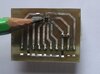
Hi J,
Does this look ok?
Note SELF TEST and NORMAL RUNNING
C.
__________________________________________________
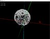
[00]Ready!
AT+C002
SELF TEST
CNTL1 22.00
ASTC 64.00
CNTL1 24.00
WIA 72 ST2 16 CNTL1 22 ASTC 0 I2C 27
-85.00, 67.00, -111.00
ASTC 0.00
CNTL1 16.00
CNTL2 0.00
i2cDIS 27.00
CNTL2 22.00
NORMAL RUNNING
-86.00,68.00,-114.00
-84.00,68.00,-106.00
-83.00,69.00,-103.00
-88.00,68.00,-110.00
-85.00,75.00,-107.00
-94.00,72.00,-108.00
-82.00,74.00,-114.00
-75.00,65.00,-109.00
-85.00,65.00,-105.00
-82.00,72.00,-110.00
-83.00,71.00,-111.00
-88.00,68.00,-108.00
-67.00,79.00,-109.00
-52.00,88.00,-112.00
-29.00,103.00,-103.00
-19.00,109.00,-115.00
-31.00,107.00,-119.00
-4.00,102.00,-114.00
18.00,108.00,-106.00
31.00,109.00,-107.00
54.00,102.00,-100.00
69.00,103.00,-113.00
73.00,93.00,-111.00
92.00,80.00,-112.00
97.00,73.00,-107.00
94.00,66.00,-116.00
95.00,57.00,-113.00
95.00,57.00,-113.00
103.00,59.00,-109.00
104.00,56.00,-114.00
109.00,57.00,-111.00
112.00,52.00,-110.00
93.00,65.00,-107.00