Continue to Site

Welcome to our site!

Electro Tech is an online community (with over 170,000 members) who enjoy talking about and building electronic circuits, projects and gadgets. To participate you need to register. Registration is free. Click here to register now.

  • Welcome to our site! Electro Tech is an online community (with over 170,000 members) who enjoy talking about and building electronic circuits, projects and gadgets. To participate you need to register. Registration is free. Click here to register now.

How 3x axis sine waves act on a Compass module Oshonsoft BASIC.

Status
Not open for further replies.

camerart

Well-Known Member
Hi,
I'm using AK8963C compass chips for use as direction findingmy projects.

Each of these chips need a BIAS calibration to correct errors, which is placed in any programs.

I use an application wirtten by YURI MAT (Not sure if that's correct) I think this link witll find it: https://github.com/YuriMat/

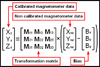
Here is the BIAS calibration calculation:

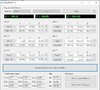
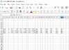
Here's an example of the 3x axis results, after calibration, also the calculated compass READing.

I would like to understand more, just how the 3xaxis work with each other, but as this is a bit complicated for me, I can only test out any examples, and try to follow.

Cheers, Camerart.
 

Attachments

  • BIAS calibration.PNG
    BIAS calibration.PNG
    29.4 KB · Views: 275
Is your question, how to do matrix math?

matrix multiplication is here

Matrix addition subtractioncan easily be found with google. It is time-consuming and tedious to set up but the math is quite easy.
 
Is your question, how to do matrix math?

matrix multiplication is here

Matrix addition subtractioncan easily be found with google. It is time-consuming and tedious to set up but the math is quite easy.
Hi G,
Now I've been given two pieces of very complicated Data sheets. As many of us are not so clever, I'll try to enter this into a spreadsheet, and hope to simplify if I can. Otherwise it will be just too much.

I think you have been following the other threads, regarding these compas modules. I can see there are 3x Axis, and can try changing entries on the spreadsheet, to hopefully, figure it out.

(Suns out so better change the oil in my gearbox :) )
Thanks C.
 
Hi,
(Oil changed :) )

Here's my first attempt of filling in a spreadsheet of this. BIAS ODS
Here's what I'm following. Bias calibration
Here's the example I'm copying.

I'm first trying to see what MAGMASTER does.
C
 

Attachments

  • BIAS example.jpg
    BIAS example.jpg
    149.5 KB · Views: 272
  • BIAS Calibration.jpg
    BIAS Calibration.jpg
    29.4 KB · Views: 275
  • BIAS ODS.jpg
    BIAS ODS.jpg
    136.4 KB · Views: 265
Hi,
I'm slowly getting the idea of how these sensors work.

There are 3x sensors inside a compass chip, each orientated at 90° to one another.

When one is horizontal (Bearing in mind that the earths magnetic forces, aren't) and turn 360° they will output through a program, numbers ranging from low to high. These numbers should be even around the circle (or logarithmic?), else they need adjusting by -+. Also the 0 and 180° positions should be opposite, else another correction.

From what I understand (Which hope to clarify, once I watch the numbers), X and Y are horizontal and at 90° to each other, where Z points upwards. So if all rotated, Z shouldn't vary much, but the other 2x should.

North is calculated using X and Y, and the calculation changes as one of the sensors gets to a weaker position then the other goes stronger.
When each sensor is horizontal and aiming at North, it's reading is 0 and at 90° its READing is highest.

Tilt error of the above calculation is corrected using the Z sensor as it gets farther away from upright.

I think this is somewhere near hopefully. Correct me if I'm wrong

C.
 
Last edited:
These numbers should be even around the circle (or logarithmic?)

I believe, neither. They should follow the matrix algebra you used for the calibration.
 
I believe, neither. They should follow the matrix algebra you used for the calibration.
Hi G,
I see! it's a little more complicated than I thought, but now I have a bit of a feel for it, I'll play at numbers for a bit, and make graphs or something, so I get it.
Thanks, C.
 
Hi,
Still playing!
Using the Magmaster box, and a compass rotating ring, each axis was READ, which gave almost circular rings, almost as expected, apart from the Z axis, which appears to have a wider range. (And it app 30° out)
What came apparent is they all ned some correction, which remined me of D/S 6.4.5. (and 8.3.11.) Self test mode. Happily I put a DRDY connection, in case of this on the PCB.
At the moment I'm just rying to understand how it is implemented and it's calculations.
C.
 
Hi,
I went back to 'GO' and checked the Magmaster PCB for anything iron, and all of the PINS I've been using are steel, plus 1x switch. I've just removed all of them, and will connect another way.

How is this for SELF TEST MODE?
C.
___________________________________________________________________________________
'SELF TEST'+++++++++++++++++++++++++++++++++++++++++++

SPICSOn
compss = 0 'CHIP SELECT COMPASS ON
SPISend 0x0a 'CONFIG CNTL1
SPISend 0x00 'POWER DOWN
SPISend 0x0c 'ASTC
SPISend 0x40 'SELF BIT= 1
SPISend 0x0a 'CONFIG CNTL1
SPISend 0x08 'SELF TEST MODE
SPISend 0x89 'ST1 0x09
SPIReceive drdy
drdy = 1 'XXXXXXXXXXXXXXXXXXXXXXXXXXXXXXXXXXXXXXXXXXXXXXXXXXXXX
While drdy = 0
Wend
SPISend 0x0c 'ASTC
SPISend 0x00 'SELF BIT= 0
SPISend 0x0a 'CONFIG CNTL1
SPISend 0x00 'POWER DOWN
compss = 1 'CHIP SELECT COMPASS OFF
SPICSOff

For i = 0 To 5
compss = 0 'CHIP SELECT COMPASS ON
addr = 82 + 1
SPISend addr
SPIReceive data
b(i) = data
compss = 1 'CHIP SELECT COMPASS OFF
Next i

x_raw.LB = b(0) 'BYTE
x_raw.HB = b(1) 'BYTE
y_raw.LB = b(2)
y_raw.HB = b(3)
z_raw.LB = b(4)
z_raw.HB = b(5)

Hseropen 9600 'After initialisation'??????????????????????????????????
Hserout "Ready!", CrLf

Hserout "SELF TEST ", #x_raw.LB, " ", #x_raw.HB, " ", #y_raw.LB, " ", #y_raw.HB, " ", #z_raw.LB, " ", #z_raw.HB, CrLf

'END SELF TEST'++++++++++++++++++++++++++++++++++++++
____________________________________________________________________________________________________________________________________
 
Hi,
I've got the Magmaster cube working with no iron to affect it.
There were a couple of errors as usual, but one worthy of note is:

There is a radio on the PCB, that send the DATA to a Terminal. The radio frequency can be changed using a button. As the previous button was magnetic, I searched my button box, but they are all magnetic, apart from a little reclaimed bit of PCB with 2x buttons on it. I took one off, and added it to the radio wires, and insulated it with heatshrink. I tested the button through the plastic and all was ok. While testing this morning, I pressed the button, but it was pushed on. It had hardened overnight and held it on. I ususally cut a hole for the nib, but this time it seemed ok so I left it. A fault that could have taken a long time to find, apart from by accident, as today. So now it's working.

Next a few more tests, then try the 'self test' program.
:)
C.
 
Hi,
Here is the self test program, I hope it's correct?

Plus here is the terminal view of a 360° rotation.

J said a while back that Z should be all '-' and now they are :)

Now I've got to find out if all 255's is what's expected from the self test. I suppose that a magnet placed next to a sensor, would take it to 255. Does it then zero the READings?

I also suppose that the Z READing should be all the same, providing that I mounted the module all square (Doubtfull)
C
---------------------------------------------------------------------------------------
[00]Ready!
SELF TEST 255 255 255 255 255 255
AT+C002
-108.00,224.00,-316.00
-104.00,232.00,-316.00
-114.00,226.00,-312.00
-114.00,234.00,-314.00
-105.00,225.00,-317.00
-110.00,224.00,-312.00
-112.00,226.00,-322.00
-125.00,217.00,-317.00
-134.00,224.00,-320.00
-153.00,211.00,-317.00
-167.00,209.00,-321.00
-169.00,197.00,-319.00
-183.00,183.00,-315.00
-203.00,175.00,-317.00
-203.00,165.00,-317.00
-210.00,146.00,-318.00
-215.00,129.00,-319.00
-209.00,103.00,-315.00
-207.00,91.00,-313.00
-200.00,80.00,-306.00
-194.00,56.00,-312.00
-184.00,46.00,-318.00
-171.00,35.00,-315.00
-173.00,11.00,-315.00
-147.00,15.00,-319.00
-129.00,3.00,-309.00
-103.00,-3.00,-313.00
-90.00,-2.00,-312.00
-70.00,6.00,-316.00
-39.00,11.00,-317.00
-24.00,36.00,-318.00
-23.00,39.00,-319.00
-4.00,68.00,-316.00
3.00,85.00,-309.00
6.00,114.00,-316.00
12.00,140.00,-318.00
-5.00,165.00,-319.00
-17.00,189.00,-313.00
-42.00,202.00,-320.00
-59.00,223.00,-321.00
-90.00,230.00,-314.00
-103.00,233.00,-319.00
-112.00,236.00,-316.00
-111.00,229.00,-305.00
-108.00,236.00,-314.00
-114.00,230.00,-314.00
-118.00,232.00,-318.00
 

Attachments

  • 18F4520 INT8MHz HC12, AK8963C PCB3 XYZSELF_TEST 120920.txt
    5.3 KB · Views: 233
In self test, you have the old error ( look msg #10 )
addr = 83 + 1
change to addr= 0x83+i

This will loop forever, when drdy is 0 the first time.
SPIReceive drdy
While drdy = 0
Wend
 
In self test, you have the old error ( look msg #10 )
addr = 83 + 1
change to addr= 0x83+i

This will loop forever, when drdy is 0 the first time.
SPIReceive drdy
While drdy = 0
Wend
Hi J,
Is this better?

I notice with the DRDY REG set to 0x82 I'm getting 255 255 for X, but this seems wrong?
C.

_______________________________________________________________________________________
[00]Ready!
SELF TEST 255 255 190 0 164 254
AT+C002
-210.00,202.00,-344.00
-221.00,197.00,-343.00
-206.00,196.00,-336.00
-209.00,191.00,-343.00
-209.00,189.00,-345.00
-207.00,195.00,-349.00
-209.00,203.00,-343.00
-212.00,190.00,-350.00
-208.00,196.00,-346.00
-204.00,194.00,-344.00
-206.00,200.00,-342.00
-205.00,195.00,-341.00
-209.00,193.00,-343.00
-206.00,198.00,-338.00
-202.00,196.00,-348.00
-199.00,197.00,-343.00
-210.00,202.00,-344.00
-213.00,199.00,-337.00
-213.00,199.00,-341.00
-206.00,198.00,-346.00
-208.00,204.00,-342.00
-208.00,192.00,-342.00
-213.00,197.00,-349.00
 

Attachments

  • 18F4520 INT8MHz HC12, AK8963C PCB3 XYZ-SELFTEST 1209202.txt
    5.4 KB · Views: 247
While drdy = 0
<--------Data ready needs to be read also here.
Otherwise this is an infinite loop
Wend
 
While drdy = 0
<--------Data ready needs to be read also here.
Otherwise this is an infinite loop
Wend
Hi J,
Do you mean like this?
________________________________________________________
dredy:
While drdy = 0
SPISend 0x82
SPIReceive drdy 'Is this checking DOR (AND) DRDY for 0????????????
For i = 0 To 5
compss = 0 'CHIP SELECT COMPASS ON
addr = 0x83 + i
SPISend addr
SPIReceive data
b(i) = data
compss = 1 'CHIP SELECT COMPASS OFF
Next i
Wend
Return
________________________________________________________

result:
[00]Ready!
SELF TEST 72 155 3 32 255 206
AT+C002
-227.00,211.00,-341.00
-239.00,211.00,-343.00
-231.00,199.00,-345.00
-232.00,212.00,-346.00
-230.00,210.00,-340.00
-233.00,213.00,-341.00
-227.00,203.00,-355.00
-221.00,215.00,-339.00
-230.00,212.00,-340.00
-229.00,207.00,-347.00
-223.00,203.00,-339.00
-227.00,213.00,-345.00
-228.00,212.00,-350.00
-229.00,205.00,-335.00
-228.00,202.00,-340.00
-225.00,211.00,-343.00
-234.00,208.00,-348.00
-237.00,213.00,-345.00
-233.00,203.00,-339.00
 
Something like this.
What makes ready bit go high?

dredy:
Testrdy
SPISend 0x82
SPIReceive drdy
If drdy.0 = 0 then ' Test drdy bit
goto Testrdy
Endif

For i = 0 To 5
compss = 0 'CHIP SELECT COMPASS ON
addr = 0x83 + i
SPISend addr
SPIReceive data
b(i) = data
compss = 1 'CHIP SELECT COMPASS OFF
Next i
Return
 
Status
Not open for further replies.

Latest threads

New Articles From Microcontroller Tips

Back
Top