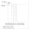
I have built the circuit below, all works fine but I'm a bit alarmed at the resisters as they get very hot,
(you wouldn't want to put your finger on them for too many seconds)
Is this O/K or have I got summat wrong.
Bazza
Hi,
There are more than a couple things to think about here.
First, you can not tell the temperature of a resistor by using your finger. You can use an IR temperature gun however. Fingers are very misleading though so you should avoid that.
Second, the only way to know if the temperature is too high for the resistor to survive is to look up the specs on the data sheet and measure with an IR gun. Some resistors can take very high temperatures like 100 degrees C, while for others that is the top end of their working temperature so you dont want to allow that.
Third, if the resistor can not get free air flow then a 2 watt resistor could overheat and burn out when it only dissipates 1/10 of a watt (one tenth of one watt). That's because heat needs a place to go or else the temperature rises forever until it does get a place to go.
Fourth, sometimes you can not run the resistor at a higher temperature even if the specs say you can. That's because it may be mounted close to another component that could melt or otherwise break down.
So the rules are:
1. Measure the temperature with an IR gun or other probe.
2. Check the temperature specs on the data sheet.
3. Make sure it has free air flow.
4. Make sure it is not mounted close to a heat sensitive component.
5. A rule of thumb is to run the resistor at one half it's power rating or less.
Note there may be times when you just dont want the resistor getting too hot. The temperature rise is closely related to the surface area of the resistor, so the larger the surface area the cooler it stays provided it can get free air flow. That means the bigger the resistor the cooler it stays. I like to keep my resistors cool so i always use overrated parts whenever possible. If you overrate by a factor of 4 they stay nice and cool. This helps a lot when they are enclosed in small packages.