Continue to Site

Welcome to our site!

Electro Tech is an online community (with over 170,000 members) who enjoy talking about and building electronic circuits, projects and gadgets. To participate you need to register. Registration is free. Click here to register now.

  • Welcome to our site! Electro Tech is an online community (with over 170,000 members) who enjoy talking about and building electronic circuits, projects and gadgets. To participate you need to register. Registration is free. Click here to register now.

hockey shooter tutor - activates light - how trigger?

Status
Not open for further replies.

mr_fitz

New Member
Hi
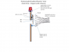
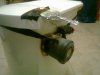
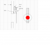
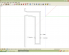
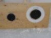
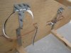
I have a question about a trigger system. I want to make a hockey shooter tutor as depicted in the images below. The puck passes through a hole in some plywood, and sets of a light to reward the shooter. Here are my ideal operation parameters:
1) light is AC - household wall plug, because this will be outside on a rink
2) putting puck through any hole should set off the light.
3) the light and trigger system should reset by itself in a short period of time - 5 seconds or less - to facilitate rapid fire sessions with several pucks. A mechanical system is fine, but I don't weld.
4) I am not an electrician or electrical hobbyist so speak slowly...:p
Thanks for sharing your thoughts.
**broken link removed**
Yes, the light will be behind a mesh barrier so shooters don't pick it as target #6!
**broken link removed**
 
hi,
What diameters are the holes and the pucks.??

Also must the puck be a 'regulation' type puck. eg: could it be 'doctored' to include say a small magnet.?
 
hi,
What diameters are the holes and the pucks.??

Also must the puck be a 'regulation' type puck. eg: could it be 'doctored' to include say a small magnet.?

The diameter of the holes is somewhat flexible, but I was thinking in the neighbourhood of about 8 inches dia.
Diameter of a puck is 3 inches by 1 inches height.
I would rather not doctor the pucks...meant to be used on outdoor rink...pucks get lost easily in the snow despite backstops... about 50 pucks get used throughout the winter. If this is relatively easily done with cheap magnets, sure I am willing to drill 50 holes and backfill with silicone or somesuch.

Some sort of active sensor like the ones protecting us from being squashed by our garage door (opener) cannot be cheaply purchased/incorporated? With the configuration in the images, this would "only" require 3 sensors - if the middle hole is removed or lowered to the bottom row, 2 sensors?

hi,
The requirement of an IR system would mean the beam would have to be broken by the 3in dia puck over a 8in dia hole.

If a simple single beam path could be used you would only require two beams, top left down to bottom right and top right down to bottom left.
The problem is the beam width required to cover a 8in dia hole.

The magnet idea was to use a 8in dia coil around each hole and detect the magnet passing thru the hole.

I am sure it can be done, we will look it over..
 
How about skipping the nets for a pan-sized metal target, could be plywood covered. Think of a rain-cap/flapper valve atop a diesel exhaust stack. The target swinging back unloads a micro-switch to start a one shot 555 circuit for the light/buzzer.
 
That sounds like it to me. Or you could put the same flapper in the hole just like your picture. Whatca think?
 
IMO an IR sensor circuit is easiest. Just use mirrors and hopefully they don't fog up?
If you use a funneling setup so all the holes are attached to one output, like a pool table then only one sensor is needed using two IR emitters/detectors.
Large diameter PVC drain pipe comes to mind
 
Okay MrDEB, since using IR sensors is what I originally had in mind I am curious as to what precisely this would look like. 1) Would you please post a link(s) to the parts you are referring to ("sensor", "IR emitters/detectors" << these are different parts?) - I am partially concerned about cost here - minus the battery and light I can probably do the flapper/magnetic switch system for under $50 - would the IR system be under $100 say? 2)Would you please describe in a bit more detail what you mean by funnelling? I thought that passing two "beams" across each hole would solve the puck to hole size issue. Does funelling solve this problem as well?
3) In addition to fog, snow and frost are potential issues on an outdoor rink - this would concern me.

By the same token, I am not sure how well these magnetic switches will hold up to the kids' slapshots over time - hence the appeal of the "active"? IR system.
thanks.
 
Last edited:
I would imagine that IR LEDs mounted to the back of that plywood would take a beating, miss the target and the puck slams the other side of the component. Get some kid with Gretzky like power and I wonder how often you'll be replacing parts. *Shrug*
 
nickelflippr,
Does the image below pretty much capture your approach? I like that there is no need for wire on the flap itself, which after many uses in the cold may be prone to breaking i.e. the magnetic switch approach. I see four challenges though.
1)mounting this switch securely to the backboard - I am sure it can be done though.
2) ensuring the flap contacts the rollover - something would have to be mounted on the back of the flap.
3) the return trip of the flap - may get caught up on the rollover and not return to the start position.
4) QUESTION
Not being electrically minded...does this switch work on a 12v dc circuit as that particular one is identified as "Contact Voltage AC Nom:277V"? I cannot find anything using "12V rollover switch" as search terms.

If somebody can find me a switch for 12V, I might just try this on at least one flap and conduct a long term comparison with the magnetic switch approach.

**broken link removed**
thanks!
 
Last edited:
nickelflippr,
Does the image below pretty much capture your approach? I like that there is no need for wire on the flap itself, which after many uses in the cold may be prone to breaking i.e. the magnetic switch approach. I see four challenges though.
1)mounting this switch securely to the backboard - I am sure it can be done though.
A short piece of 1"-1-½" iron angle would keep things solid.
2) ensuring the flap contacts the rollover - something would have to be mounted on the back of the flap.
See image for no rollover scheme. Adjust switch height and or stop for contact and depression of switch in the N.O. position.
3) the return trip of the flap - may get caught up on the rollover and not return to the start position.
See above.
4) QUESTION
Not being electrically minded...does this switch work on a 12v dc circuit as that particular one is identified as "Contact Voltage AC Nom:277V"? I cannot find anything using "12V rollover switch" as search terms.
Switch will work fine for dc.

If somebody can find me a switch for 12V, I might just try this on at least one flap and conduct a long term comparison with the magnetic switch approach.

thanks!
See the my quick/crummy markup of Paint dwg in attachment for what I was thinking. If a the flapper has the right amount of mass (add weight to back) then I don't see the need for the nets.
 

Attachments

  • hockey_trainer.PNG
    hockey_trainer.PNG
    133.8 KB · Views: 394
THis is my garbage can, it is rigged to a 12v backup alarm an run with a 9v battery, the trigger is a piece of tinfoil(which is usually at 90angle, that contacts with the metal at the bottom, this is so my dog scares when she tries to eat the trash.

TO the point:

For your light id use a 12v revolving lamp(for service vehicles), and since your new i'd recommend the flapper-switches over IR, run them to a 555 timer trigger so it stays on for the 5 seconds. This way your switch just needs to be brushed and it will still go off.

then you can just use a AC-12vDC adapter for your power.


AS for the switch, just use a nail(to a wire) that stops the flapper(with tinfoil or sheet metal on back to other wire) @ 45degrees or less.. thus deflecting puck downward aswell
 

Attachments

  • Photo0039.jpg
    Photo0039.jpg
    518.1 KB · Views: 462
flapper

Following up on NF idea. The switch opens when hit. I bet you could get rid of the nets and just use a piece of sheet metal at the bottom of the board to return the pucks to the front.
 

Attachments

  • HP.PNG
    HP.PNG
    24.1 KB · Views: 309
IR idea

very simple approach then have all the target holes funnel into one sensor tube OR have a sensor for each target hole and then have each target with a score amount.
Then as the puck goes into each target the score can be added up.
Easy using a micro-controller.
as for parts from Mouser Electronic Components & Supplies
SFH 4258-Z emitter SMD
SFH 310-2/3 dector through hole
depending on number of sensors wanted a complete electronics circuit could be had for well under $50 using a 18F1320 PIC, 6 or so sensors and maybe a digital readout for score or just have a bunch of LEDs
the foam would slow the puck down thus preventing any damage to the sensors which are recessed.
 

Attachments

  • hocky target.PNG
    hocky target.PNG
    70 KB · Views: 284
prototype, help with wiring?

Hi all.
Thanks for all the ideas. I have more questions...see below.
MrDeb NOW I get it, thanks for image. A friend of mine was planning to do something like that - but without the light and sensors - with the pucks spitting back out the bottom of the boards.
Doggy__ I had thought of simlply wiring my strap/stop and flapper bar/stop (see attachments) like your dog alarm especially if my delay timer arrives before my magnetic swithes.

See the attached files to see where I am at - these are two prototypes I cut out of spare plywood rather than make mistakes on my existing rink boards. I have tried to keep things as simple as possible so the flapper/target just dangles slightly off vertical on a hinge with a copper strapping stop. The bungee I had holding the flap tight to the board is actually counterproductive since the impact of pucks hitting the boards around the hole (misses) will actually open the flapper slightly while simply letting the flapper/target hang avoids this - no amount of jarring by a puck moves the flapper on the left (back view). The white ring around the one on the right (front view) is aluminum flashing to prevent wear around the hole as you can see happened around the hole on the left (front view) without the flashing. Target/flapper is covered in old car mat carpet.
I am still waiting for my magnetic switches and delay timer to arrive, but given that I don't know much about wiring, I thought I would get the setup straight in my head before the parts arrive. See the attachment with my first attempt at how it will be wired.

QUESTIONS
I assume this is to be wired in series? If one of the N/C magnetic switches opens the light goes on, then shuts off after 5 seconds. I am particularly unsure about what to do with the delay timer. Which do I use tgr, com, n/c? Are the jumpers correct? Here is the delay timer manual which I am sure makes much more sense to many of you.
Thanks!
mr_fitz
 

Attachments

  • hockey_shooter_tutor_prototype_front.jpg
    hockey_shooter_tutor_prototype_front.jpg
    120.7 KB · Views: 304
  • hockey_shooter_tutor_prototype_back.jpg
    hockey_shooter_tutor_prototype_back.jpg
    138.8 KB · Views: 867
  • hockey_shooter_tutor_w_light_wiring1.gif
    hockey_shooter_tutor_w_light_wiring1.gif
    137.1 KB · Views: 347
Last edited:
One major problem with your design is the puck MIGHT bounce off the wood covering the hole then nothing happens except the puck goes off to where ever it wants.
 
Pretty sure that Diagram 3 of the manual would be the setup. That has the mag switches as the trigger, which energizes the relay when opened. The light + would be hooked up to the relay COM, and makes contact with the relay N/O (jumpered to (batt)+) for the duration of the delay.

Looks like the shooters would be penalized for a low skidding shot on the ice. Could make the bottom holes like an arch, with the bottom of the flapper right on the ice?
 
ALMOST had it

but you need to take another wire from your + terminal and feed it to NO pin (on your box)

NEXT disconnect the light completely, take the negative wire from revolving light and add it to battery ground, take the +ve light wire and add it to RELAY GROUND on your box.

3rd....your switches are wired in series, you want them in parallel, take all the bottom ends of switches and wire them to BOX TRIGGER, then put a 22K ohm resistor from trigger to ground, and take the top ends of switches and tie them to Battery +ve

ALSO you need to take JP2 set it to "one shot" , JP5 in your box and set it to a +ve trigger(see in your manual)
according to the manual i'd guess that just brushing the contacts on the flappers should be OKK, but it doesn't specify a trigger time.
 
Status
Not open for further replies.

Latest threads

New Articles From Microcontroller Tips

Back
Top