Continue to Site

Welcome to our site!

Electro Tech is an online community (with over 170,000 members) who enjoy talking about and building electronic circuits, projects and gadgets. To participate you need to register. Registration is free. Click here to register now.

  • Welcome to our site! Electro Tech is an online community (with over 170,000 members) who enjoy talking about and building electronic circuits, projects and gadgets. To participate you need to register. Registration is free. Click here to register now.

Hobbist Trying to Learn Circuits

Status
Not open for further replies.

Talguy

New Member
Hi all,

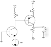
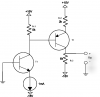
I picked up a book to help teach myself the basics of electronics. I am currently stuck trying learn transistors, see attached circuit. Basically I can solve the NPN bjt and get the right values for it, IB1=9.9uA, IC1 = 0.99mA, but i can't solve the rest of the circuit. When I try to solve the rest of the circuits I get the wrong values when comparing them to multisim. Could someone help me out.
 

Attachments

  • problem..png
    problem..png
    48.6 KB · Views: 316
Here are the basic steps to solve the circuit. You just follow the signal through the amp.

You have already calculated the collector current the NPN.

Next calculate the voltage drop through its collector resistor due to this current. Subtract that from the supply voltage to get the collector voltage. (This neglects any base current from the right transistor, but it's small so we can ignore it at this point).

This NPN collector voltage is also the PNP base voltage. Use the typical Si transistor base-emitter voltage drop of 0.65V to calculate the PNP emitter voltage.

Subtract that from the supply voltage to give the voltage drop across the PNP emitter resistor. Use that to calculate the emitter current.

From that you should be able to now calculate the PNP collector current and the voltage drop across the collector resistor to give Vo.

For improved accuracy you can now to back and include the base current of the PNP in your calculations.
 
If we assume that β = ∞ and Vbe = 0.65V then voltage on 5KΩ resistor is equal :
VRc1 = 1mA * 5KΩ = 5V
And from II Kirchhoff's law for PNP input loop we can write
VRc1 = Vbe2 + VRe2 so VRe2 = 5V - 0.65V = 4.35V
And if we know the voltage on the Re2 we can easily determine Ie2.
Ie2 = 4.35V/2KΩ = 2.175mA
And then VRc2 = 2.1mA * 6KΩ = 12.6V.
And finally Vo = 12.6V - 15V = -2.4V
 

Attachments

  • problem...png
    problem...png
    36.4 KB · Views: 274
Last edited:
Sorry I forgot to ad beta=100 and that |Vbe| = 0.7V. That aside I can defiantly follow the above steps and see if i get the correct final result.
 
OK so if β1 = β2 = 100 and Vbe= 0.7V then:

Ic1 = β / (β+1) *1mA = 0.99mA

VRe2 + Vbe2 = (Ic1 - Ib2) *Rc1
Ib2*(β2+1)*Re2 + Vbe2 = (Ic1 - Ib2) *Rc1
Ib2*(Rc1 + Re2*(β+1 ) + Vbe2 = Ic1*Rc1
Ib2 = ( Ic1*Rc1 - Vbe2 ) / (Rc1 + Re2*(β+1 ) = 4.25V / 207KΩ =20.533uA
then
Ie2 = (β+1)*Ib = 2.073mA
Ic2 = β * Ib = 2.053mA
VRc2 = Ic2 *Rc2 = 12.318V

Vo = 12.318V - 15V = -2.682V
 
Status
Not open for further replies.

Latest threads

New Articles From Microcontroller Tips

Back
Top