hi,
If you used a 8255 PIO to connect to the 6116 SRAM, you would do the following write/read sequence.
Change the PIO's portA to output.
Set the PIO's portA to say the 8 bit data you want to write to the SRAM.
Then set the PIO's portB and portC[low nibble] to the the address [location] in the SRAM where you want the data on portA to be written.
Then set the SRAM WR and CS low and high,[using portC[high nibble] this will write the data to the addressed SRAM location.
For reading the SRAM,
Change the PIO's portA to input.
Then set the PIO's portB and portC[low] to the the address [location] in the SRAM where you want the data on portA to be read from
Then set the SRAM CS low and high, this will place the data of the addressed SRAM location onto the portA, which the program then reads.
As you can see, the write/read cycle is much longer than the 'clock' rate.
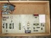
It would help if you could post a block diagram of your project.
 )
)
")