Continue to Site

Welcome to our site!

Electro Tech is an online community (with over 170,000 members) who enjoy talking about and building electronic circuits, projects and gadgets. To participate you need to register. Registration is free. Click here to register now.

  • Welcome to our site! Electro Tech is an online community (with over 170,000 members) who enjoy talking about and building electronic circuits, projects and gadgets. To participate you need to register. Registration is free. Click here to register now.

High Voltage Testing

Status
Not open for further replies.

Mity Eltu

Member
I have a circuit consisting of the following components: Doble current source set for 30A and a low impedance shunt. This is a fuse testing rig. The shunt is for ensuring that the current is very close to the rated current of the fuse. Voltage measurements are taken across the shunt. Temperature measurements are taken from the fuse to deterine thermal stability of the fuse during testing. I have been asked to find a method for data acquisition that will aloow us to measure the temp and the voltage on a bulk basis so that multiple fuses can be poled and the data collected without the need for a technitian to stand there for 30+ minutes taking data.

Here's the problem. If the fuse opens, the voltage at the shunt will be upwards of 1000V. I do not know how to properly isolte this from my measurement circuit, which I am figuring to be a 16:1 multiplexer, into a PIC microcontroller. The temperature signal can be amplified easily and fed through the multiplexer to the micro without a problem, but the voltage at the shunt could easily blow apart anything I have thought of so far.

I don't know much about electrical isolation aparently. Is there a way of attenuating this very high voltage such that it will not introduce a high voltage on the fuse during testing and be able to withstand the high voltage if the fuse should open? I'm drawing a blank on how to make this happen without the use of a current transformer, which will make this project too cumbersome and costly.

Any ideas?
 
What you didn't mention. Is the voltage AC or DC and the nominal value. What is the measuring range? i.e. The voltage your interested in measuring. You did specify a spike range. Is it OK to clamp the voltage?

Isolation amplifiers are commercially available. Spark gaps could do some limiting. Go to www.newark.com and search for "spark gap"

This **broken link removed** is "an isolating module" which is not likely to work because of the input range, but it can isolate 1.5 KV for 1 min.
 
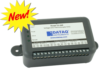
I have a "data acquisition" box. About the size of a deck of playing cards. They connect to a PC via USB or serial. Mine has 32 inputs that measure voltage. It can be set to measure every 1 second or every 5 minutes or 100 times a second etc. The data can be input into a spreadsheet program.
di-245-voltage-tc-daq-new.png

This picture is typical. There is no isolation! They can measure voltage, some measure temperature probes, current etc.

Before we fight the battle of 1000 volts and isolation. Where is the 1000 volts coming from? 30A and 1000V That's 30kw. I just don't see it. I think you are testing fuses at 30A and that could be done at 10 volts or less. Maybe there is a 1uS spike to 1000 volts. I just can't see using a 1000V supply at 30A. Then you want to do 16 fuses at one time. You can't find a 480 amp 1000 volt power supply.

Please send more information. Maybe pictures.
 
I agree with Ron, there is something odd about the testing scheme here.

The fuses may be rated at 30amp at 1000volt, but you dont need 1000volt to pass 30amp through a fuse which has a very low resistance.
Check the specification of your current source, what does it give for the open circuit voltage, which may be stated as the compliance voltage.

JimB
 
If I was making this test machine:
I can make a black box that take 12V at 0.3A in and outputs 30A for the fuse. When the fuse pops there will be a max of 10V present.
With a 12V 5A very simple power supply one could power 15 of the above 30A supplies.
Using a simple USB data acquisition box we will measure the voltage drop across the fuse and temperature.

If the fuses are at ground on one end and we watch ground loops I don't see the need for isolation.
 
This would go much better with more information as KeepItSimpleStupid mentions. Also, this could likely be done quite easily using any DAQ (Date Acquisition) device which RonSimpson gives a good example of.

Things to keep in mind are how accurate does the temperature need to be monitored and how accurate does the current need to be monitored? What is the test duration as I see you mentioned 30+ min? How many fuses do you want to test at one time? You also need to define too cumbersome or costly as to what is the budget?

A rough schematic of the existing test setup would really help as when I see shunt and numbers like 1 KV I assume the shunt is High Side?

Personally if tasked to do this I would use a DAQ like Ron mentions and write some very basic software around it. The data could be dumped into Excel as was mentioned. I likely would not use a shunt but a current transducer be it AC or DC **broken link removed**. The link being only AC examples. Anyway, you will need to provide much more information before anything of value can be suggested.

Ron
 
Hi Ron,

While we are thinking about this. I have some 30A Hall current sensors with 2000V isolation. (a last year project) That reminds me I need to call them and see if they have more work.

ron
 
Hi Ron,

While we are thinking about this. I have some 30A Hall current sensors with 2000V isolation. (a last year project) That reminds me I need to call them and see if they have more work.

ron

I know that somewhere around here I have some of the CR Magnetics sensors but don't have a clue where? :) I think both current AC and some voltage transducers. Also a bunch of shunts as well as some CTs. Years ago I got some of the DATAQ Instruments data acquisition units you show. Used a bunch of their stuff over the years. Heck, the early Starter Kits were RS232. I liked DATAQ because they are in Akron, just down the road from me and they give excellent code examples for using their products.

Since I retired last year I seldom mess with the stuff. Oh yeah, before I forget, I have at least one old Simpson panel type analog voltmeter with your name on it (Simpson), it's a 0 to 50 DCV, do you want it? Simply because it is Simpson, like your avatar. :)

Ron
 
Ron, Thanks but you should keep it in memory of me. Ron

I am afraid the last 9 years have not been good so I won't be retiring. I am on the work until I drop program.
 
Why not just use an Analogue, Micro-ampmeter with a Resistor Divider network to monitor the voltage point in question.

Shurly Anyone can see such a Meter Reading.
 
Why not just use an Analogue, Micro-ampmeter with a Resistor Divider network to monitor the voltage point in question.

Shurly Anyone can see such a Meter Reading.
He wants to measure 16 voltages and 16 temperatures over 30 minutes. It takes labor!
The voltage across the fuse is probably 0.01 volts. When the fuse is open he claims the voltage goes very high (1kv). I don't think it does.
 
So... it seems that we're discussing a variable current source with a maximum compliance (ie, open-circuit optput voltage) of 1kv. I assume this would be to test the arc-clearing ability of the fuse under test. It's not clear though if this is AC or DC - clarifying this would help.

Surely the ideal solution would be to simply place the sense shunt (or add an additional shunt) on the low side of the supply, so the voltage you're measuring is relative to ground. If you add an additional shunt, then you can size it to give an appropriate voltage swing into your data logger. It might be prudent to include a large series resistor and a zener to clamp any transients that may get picked up, but no high voltage clamping should be needed. If your supply really has a compliance up to 1kv then the additional voltage drop across an additional shunt would be completely irrelevant.

If we're interested only in the maximum current passed during the test, you may also wish to include a peak-hold circuit; this would also make the system suitable for AC.
You could then use a comparator circuit to detect the rise in voltage across the freshly-blown fuse and trigger the data logger (this would require good input voltage clamping, but with a high-impedance input this would not be a big problem)
 
I went back to post #1 and the voltage measurement is across the shunt. I misunderstood. So he is measuring current. This means the power supply does not hold at 30A very well. That can be fixed.
The 1000 volts at the shunt is probably because there are long wires and the inductive kick back of the wiring. That can be fixed.
We don't know how the temperature is measured.
I think we really don't know enough.
 
I once -over 25 years ago- visited a fuse manufacturing facility, and they had a similar setup, for QC auditing.
Since fuse testing is destructive, it is performed on a statistical basis taken from a sample of a large batch.

They used GPIB-controlled power sources, set in CC mode. The test current was set via GPIB, but if I remember correctly though, the open circuit voltage was about 12 volts.
 
Schmitt Trigger, That's how I would do it.

I think it is interesting they are measuring the temperature of the fuse. The temperature under high load will tell you much about the fuse.
I believe the temperature and (high load resistance) are very much related. A high resistance fuse will heat faster.

By passing 70% to 90% of rated current and measuring either temperature or voltage drop you could accurately predict how the fuse will react to over load conditions.

Next idea: IF it takes 1 watt of energy to bring the fuse up to the milting point, then the fuse should be very save at 1/2 watt. I could build a power supply that is in constant current mode but regulates at 1/2 watt in the fuse. (so we are not measuring temperature at 30A but measuring current at 1/2 temperature, so by interpolation we know current to pop the fuse with out taking the fuse to the edge) I think we can predict the current capacity of a fuse with out getting ti too hot and damaging the fuse.

We are too far down this road with out Mity Eltu's help.
 
When I went to visit the fuse factory, I was not looking at fuse manufacturing and testing per se, but to learn more about automated GPIB-based tester implementation.
So I didn't look at the exact details of the testing procedure.
 
Status
Not open for further replies.

New Articles From Microcontroller Tips

Back
Top